Head gimbal assembly apparatus having an actuator mounted on a mounting plate comprising a ceramic sub-plate formed on a stainless steel mounting plate

a technology of mounting plate and actuator, which is applied in the field of head gimbal assembly testing shaker, can solve the problems of high wear surface such as tooling steel, low cost and high life, and achieve the effect of accurate resonance testing of hgas and extension of usable test frequency rang

Active Publication Date: 2012-04-03
MAGNECOMP
View PDF5 Cites 20 Cited by
  • Summary
  • Abstract
  • Description
  • Claims
  • Application Information

AI Technical Summary

Benefits of technology

[0008]The present invention provides a HGA dynamic tester which exhibits fewer resonance modes within frequencies of interes

Problems solved by technology

Different mounting methods are possible, and may require a high

Method used


Image

  • Head gimbal assembly apparatus having an actuator mounted on a mounting plate comprising a ceramic sub-plate formed on a stainless steel mounting plate
  • Head gimbal assembly apparatus having an actuator mounted on a mounting plate comprising a ceramic sub-plate formed on a stainless steel mounting plate
  • Head gimbal assembly apparatus having an actuator mounted on a mounting plate comprising a ceramic sub-plate formed on a stainless steel mounting plate

Examples


first embodiment

[0024]FIG. 4 is a side elevation view of a HGA resonance tester according to the present invention. Test assembly 20 includes a mount 22, the mount comprised of a first mount piece that is mounting plate 24, and a second mount piece that is a sub-plate 26, the first and second mount pieces being made of two different materials. The key is that one of the materials has a high modulus to density ratio. Sub-plate 26 has a high stiffness which significantly increases the natural resonant frequency of the entire system.

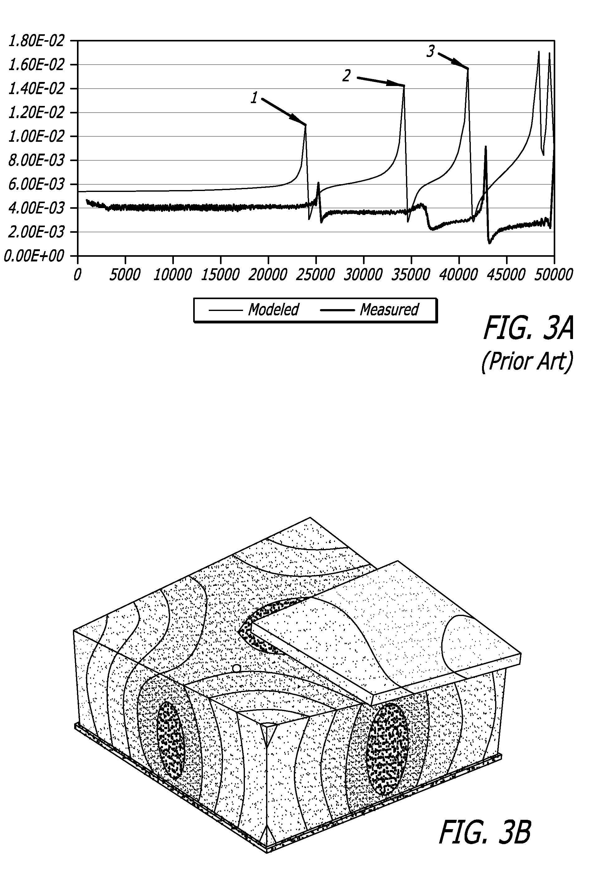
[0025]FIG. 5 shows the modeled system response in shear for the embodiment of FIG. 4. It shows that the first resonance mode is greater than 50,000 Hertz. This demonstrates that the shaker baseline can be such that there are no modes between 1000 and 50,000 Hertz, which is the entire test range for HGA / suspension resonance testing. In this simulation the 440 C stainless steel mounting plate 24 and the SiC sub-plate 26 were equal in thickness.

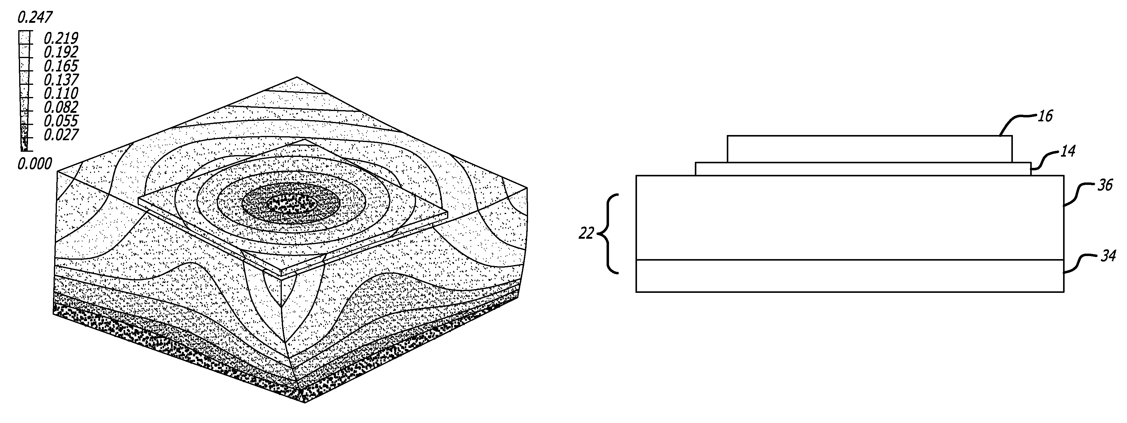
[0026]FIGS. 6-8 are displacemen...

second embodiment

[0032]Increasing the thickness of the SiC plate and reducing the thickness of the 440 C plate will increase the frequency of all resonant modes as well. FIG. 9 shows the invention in which the sub-plate 36, made of the high modulus to density ratio material, is significantly thicker than mounting plate 34, which is made of the 440 C material. Optimally sub-plate 36 takes up most of the thickness of mount 22, with mounting plate 34 being only thick enough to provide a ferromagnetic mass and surface to be held sufficiently securely by the electromagnetic test assembly holder.

[0033]In a third embodiment (not shown) the mount plate 26 is eliminated altogether, and the entire mount 22 is made of SiC or other suitable material having a high modulus-to-density ratio. In such an embodiment, the test assembly would need to be held in place by some method other than ferromagnetism, such as via clamping, bolting, or other methods.

[0034]Although sub-plates 26 and 36 are disclosed as being SiC i...


PUM


Abstract

A test assembly for a disk drive suspension head gimbal assembly includes a steel mount plate and a mount sub-plate of a material such as silicon carbide having a modulus of elasticity to density ratio that is significantly higher than the ratio for stainless steel. Preferably the mount plate and the mount sub-plate taken together have a first resonant shear frequency of greater than 50 KHz, which is generally greater than the frequency range of interest for testing head gimbal assemblies. The high modulus of elasticity to density ratio helps to ensure that any shear mode resonances of the test assembly occur at frequencies that are higher than the frequencies of interesting for head gimbal assembly shear resonance testing purposes.

Description

CROSS-REFERENCE TO RELATED APPLICATIONS[0001]This application claims the benefit of U.S. Provisional Patent Application Ser. No. 61 / 092,017 filed Aug. 26, 2008.BACKGROUND OF THE INVENTION[0002]1. Field of the Invention[0003]This invention relates to the field of a test apparatus for head gimbal assemblies for hard disk drives. More particularly, this invention relates to the field a head gimbal assembly test shaker for resonance testing of head gimbal assemblies, having improved system mode performance.[0004]2. Description of Related Art[0005]Magnetic hard disk drives used for data storage typically included a head gimbal assembly (HGA) which carries a slider which includes a read / write transducer for writing data to, and reading data from, the disk surface. As recording track densities increase and servo bandwidths also increase, there is a need to test HGA resonance and other dynamic characteristics at high frequencies. U.S. Pat. No. 7,034,372, assigned to the assignee of the pres...

Claims


Application Information

Patent Timeline
IPC IPC(8): H01L29/84G11B5/48
CPCG11B5/455G11B5/4806G11B5/4833G11B5/4873
Inventor HOLAWAY, BRETT
Owner MAGNECOMP
Why Eureka
Try Eureka