
Data communications system and data communications method between distributed controllers connected by serial bus

a data communication system and serial bus technology, applied in the direction of coding, instruments, code conversion, etc., can solve the problems of increasing the memory of other stations proportional to the capacity, delay time (latency) to reflect the data written, etc., to avoid data collision without increasing the load on data communication, and improve the effective data communication speed , the effect of maximizing the utilization efficiency of the bus

Inactive Publication Date: 2012-04-03
HITACHI LTD
View PDF17 Cites 1 Cited by
  • Summary
  • Abstract
  • Description
  • Claims
  • Application Information

AI Technical Summary

Benefits of technology

The present invention aims to solve the problem of delay in data communication caused by the large amount of shared data being shared between multiple stations. The invention proposes a data communication system that has the small worst latency of communication not being affected by the amount of shared data being large or small. The system should have the fast communication speed, should have the small software load of the processor, and should adopt the serial connection method which has small wiring amount and is advantageous for small space mounting. The invention proposes a method for transferring transmission rights between processing devices connected via a serial bus, and a method for managing the transmission rights. The invention also proposes a system for generating error correction codes and retransmitting data if there are errors. Overall, the invention aims to realize a data communication system with high efficiency and speed.

Problems solved by technology

However, as the method makes the memory data of all the stations be consistent by periodically transmitting all the memory data shared between the plurality of stations on the serial bus, there is a problem that the delay time (latency) to reflect the data written in the memory of a certain station to the memory of other stations increases in proportion to the capacity of the memories which share the data.

Method used


Image

  • Data communications system and data communications method between distributed controllers connected by serial bus
  • Data communications system and data communications method between distributed controllers connected by serial bus
  • Data communications system and data communications method between distributed controllers connected by serial bus

Examples


Embodiment Construction

[0044]One embodiment of the present invention will be explained below referring to accompanying drawings.

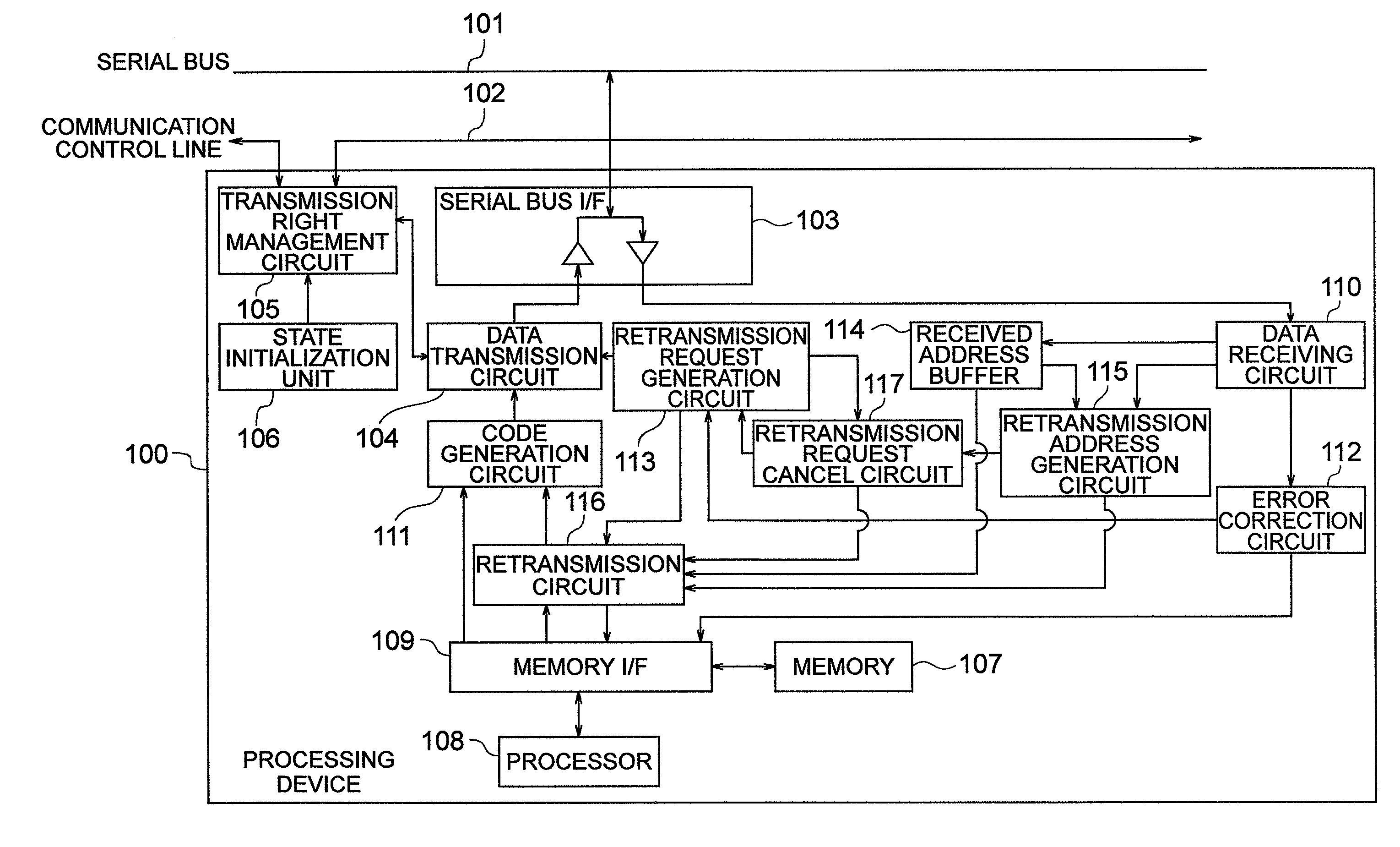
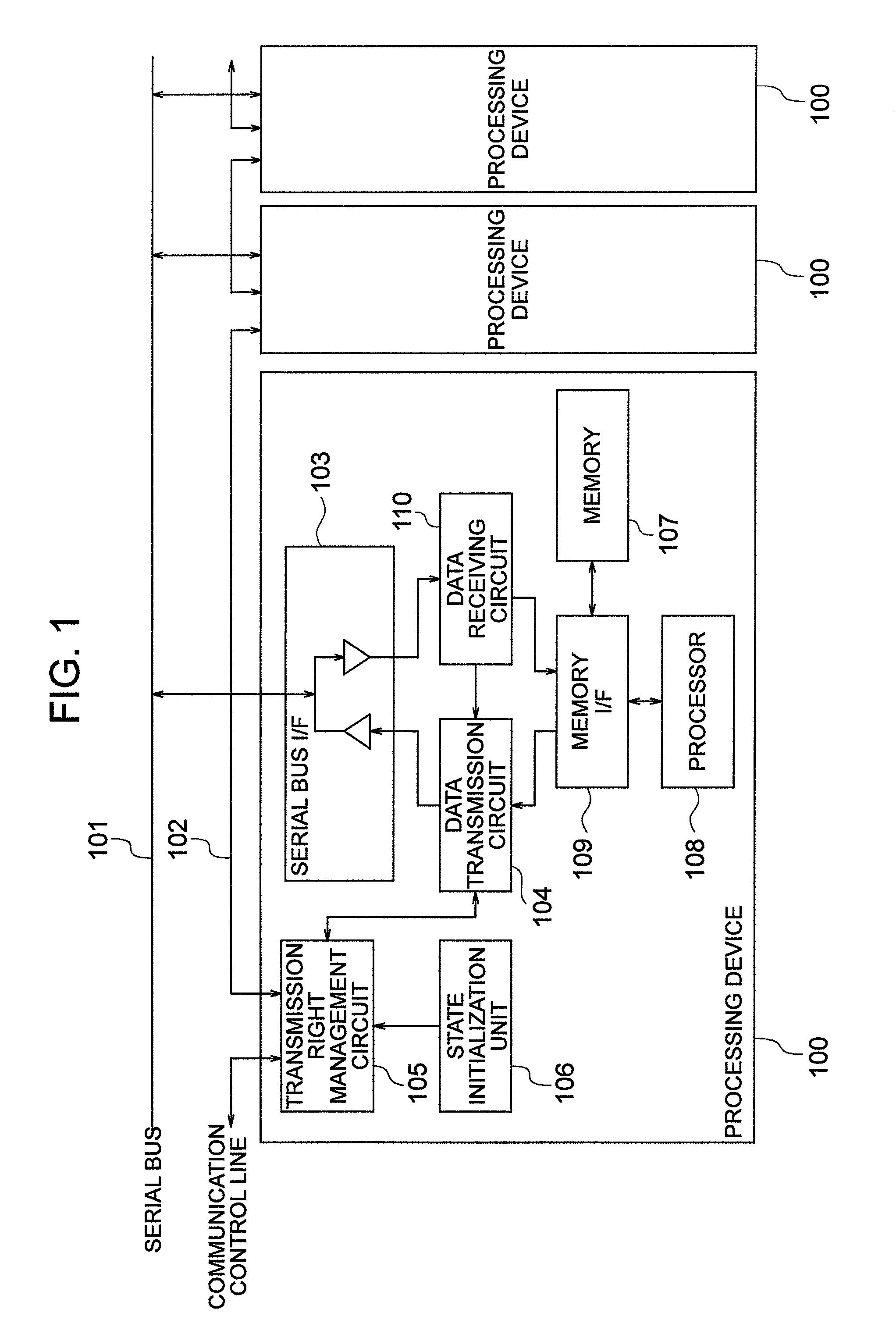
[0045]FIG. 1 shows an example of configuration of a data communications system of this embodiment. This embodiment is configured in that a plurality of processing devices 100 are connected to a serial bus 101 via a serial bus interface (I / F) 103, and between each processing device 100 it is sequentially chained, for example like a daisy chain, by communication control line 102 which performs the transfer of the data transmission right of the serial bus 101. Although the end part of the communication control line 102 is in the open state in FIG. 1, it is also possible to configure connecting the communication control line of the open part to each other and making it in the ring form.

[0046]Next, it will be explained about the configuration of the processing device 100 referring to FIG. 1. Here, as the processing devices connected to the serial bus 101 all have the same configuratio...


PUM


Abstract

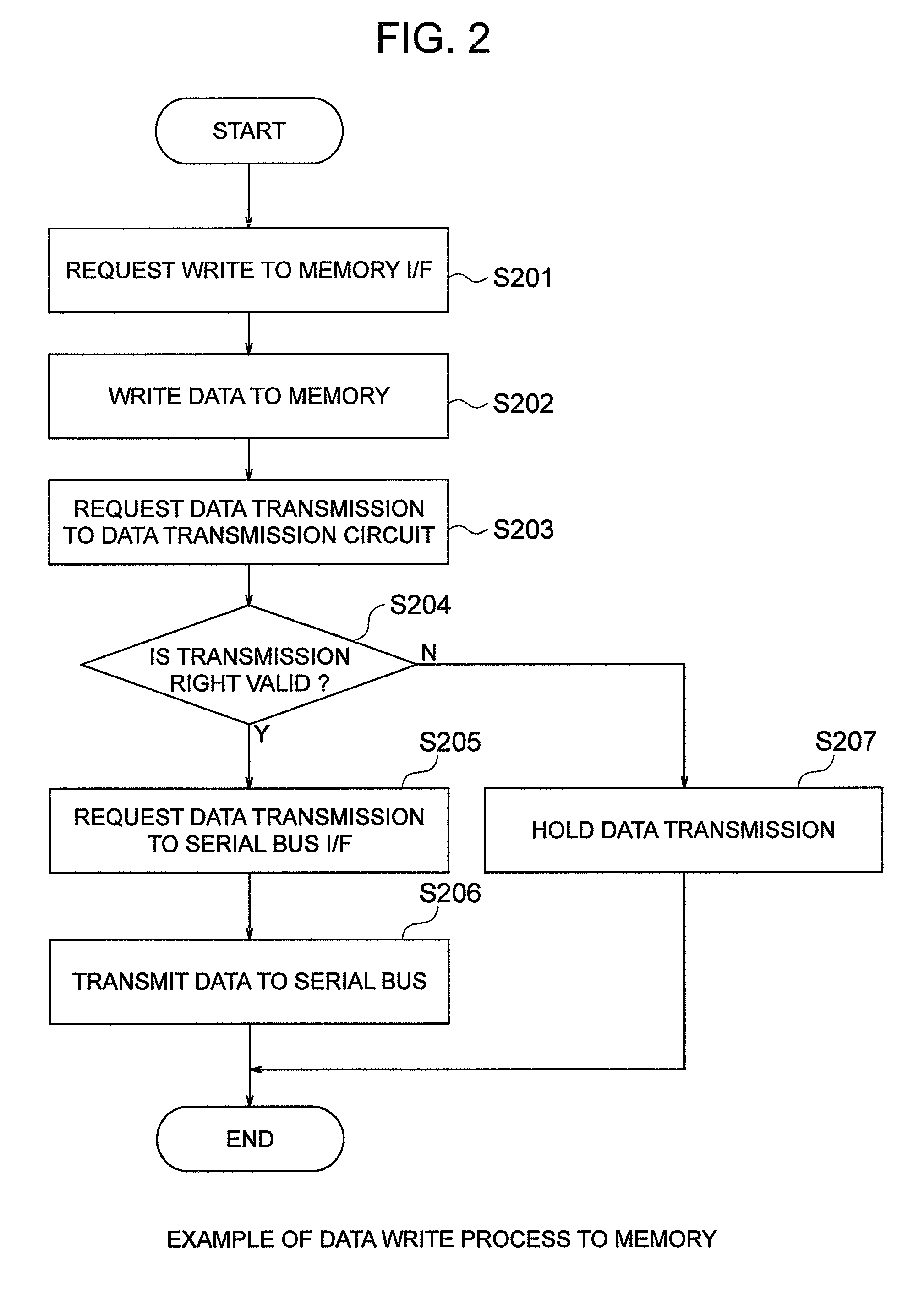
A data communications system having a plurality of processing devices connected to a serial via a serial bus interface. The processing device provides a communication control line which connects each processing device in order and performs the transfer of transmission right of the serial bus, a transmission right management unit which is connected to the communication control line, performs the transfer of the transmission right and manages the state of the transmission right within its own processing device, a data transmission unit which starts data transmission when the transmission right is valid and holds the data transmission when the transmission right is invalid, and a state initialization unit which sets the initial state of the transmission right so that the transmission right of only one processing device is made to be valid at the initialization.

Description

BACKGROUND OF THE INVENTION[0001]The present invention relates to a data communications system and a data communications method to share memory data in real time between a plurality of distributed controllers connected by a serial bus.[0002]In built-in control equipment such as a robot, etc. on which multiple devices such as a sensor, an actuator, etc. are mounted and which needs complicated control using those devices, a configuration which performs cooperative control controlling those multiple devices by dividing them in some distributed controllers and having them communicate with each other is often adopted. There are some reasons why the configuration of distributed control type like this is adopted, but the reasons particularly important as built-in control are to make the equipment smaller by alleviating the concentration of wiring, to improve the noise problem with the shortening of the wiring distance, and to enhance the reliability. Also, in order to realize the configura...

Claims


Application Information

Patent Timeline
Patent Type & Authority Patents(United States)
IPC IPC(8): H03M13/00
CPCG06F13/37H04L1/1829
Inventor IKE, KATSUHISA
Owner HITACHI LTD
Learn More