Multiple voltage DC to DC resonant converter

a resonant converter and multi-voltage technology, applied in the direction of electric variable regulation, process and machine control, instruments, etc., can solve the problems of significant changes in reflected leakage inductance, and achieve the effect of reducing resistance of this resistor, improving efficiency of the entire circuit, and reducing current in the field effect transistor

Active Publication Date: 2012-04-10
ERP POWER
View PDF8 Cites 9 Cited by
  • Summary
  • Abstract
  • Description
  • Claims
  • Application Information

AI Technical Summary

Benefits of technology

[0021]There is, in effect, an outer loop, which is a resonant synchronous resonance loop, and an inner loop, which is an amplitude modulation loop in the resonant circuit of the invention. The synchronous resonance loop is driven by at least one field effect transistor, usually a pair of field effect transistors and up to four Fets.
[0022]Conventional resonant frequency converters frequently will use a fixed timer which can set the output time on synchronous field effect transistors. The problem with the fixed timer is that you cannot stop the reversing cycle and this can be a large problem with a power supply. To solve this problem, the circuit of the present invention uses an arrangement identical to trailing edge modulation to shut down each of the synchronous transistors at the proper time, that is when they are no longer able to conduct backwardly. In this way, the resonant converter will change its frequency and there will be no need for voltage blocking. The synchronous transistors also do not need any diodes and they will turn off at the proper times.
[0023]Another important aspect of the present invention is that when the synchronous field effect transistors are turned on, there is always an intrinsic diode across the drain source. When the field effect transistors are required to be turned on, the intrinsic diode is always forwardly and properly biased so that the voltage comes up, and this turns on each such diode. When the transistor is turned on, the voltage of that transistor drops to the voltage drop across a resistor in circuit with that transistor, and which is a five milliohm resistor. The resistance of this resistor is much lower than the forward voltage of the diode. In this way, the efficiency of the entire circuit is substantially improved.
[0024]Due to the fact that the invention does not use power diodes which have large losses, it is possible to modulate the amplitude of the drive to these transistors so that the resistance of the transistors can be controlled from five milliohms to about one megaohm (at full saturation). In essence, the invention enables one to obtain complete control of the outputs, making the invention a regulated circuit, without the need for a expensive components.
[0025]In the approach commonly used in the prior art, when the voltage increases on the field effect transistors, a comparator is provided, and which operates as a one-shot, providing a timing control. This will turn off the transistors at a proper pre-set time. Moreover, the transistors will be turned off before the voltage reverses. The current may still be positive in the transistor and this is equivalent to the drive used on the multiple output voltage transformer of the invention. When the timer is effectively turned off, the current in the field effect transistor can go negative. In essence, the current will start to move in a reverse direction and discharge the output back into itself. The problem with the timing arrangement just described, is that if the current becomes negative, it can stay negative and visa versa. Thus, this is not really an operative condition. This problem was solved in the prior art by use of more than one power transformer. In other words, the transformer for a 12 Volt output transforms, then transforms for a 5 Volt output and then transforms for a 3.3 Volt output.
[0026]In the present invention, trailing edge modulation is used, as aforesaid. Thus, as the secondary voltage of the field effect transistor is increasing, if there is a slight decrease in voltage, that means the resonant cycle for that output is over. It does not mean that the timer voltage is reversed. In the circuit of the invention, each transistor has its own driver and its own comparative circuit. There is no need for a fixed timer. In this way, there is effectively a separate timing signal for the 3.3 Volt winding, a separate signal for the 5 Volt winding and one for the 12 Volt winding. In effect, this is trailing edge modulation because the trailing edge is modulated where it needs to be.

Problems solved by technology

Unfortunately, the leakage inductance value is a function of the secondary winding coupling.
This varying secondary voltage means that there will be very significant changes in reflected leakage inductance when it comes to the resonating inductance.
However, it is apparent that any circuit design requires the resonant circuit to remain operational under most conditions of cross loading.

Method used


Image

  • Multiple voltage DC to DC resonant converter
  • Multiple voltage DC to DC resonant converter
  • Multiple voltage DC to DC resonant converter

Examples


Embodiment Construction

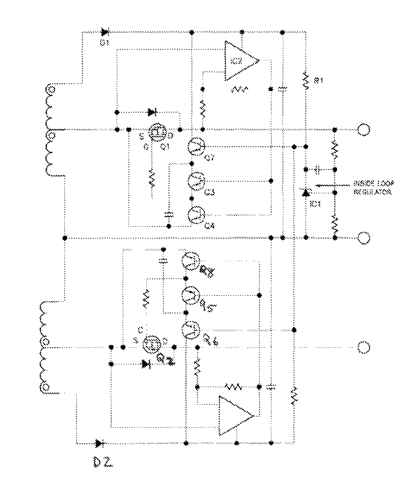
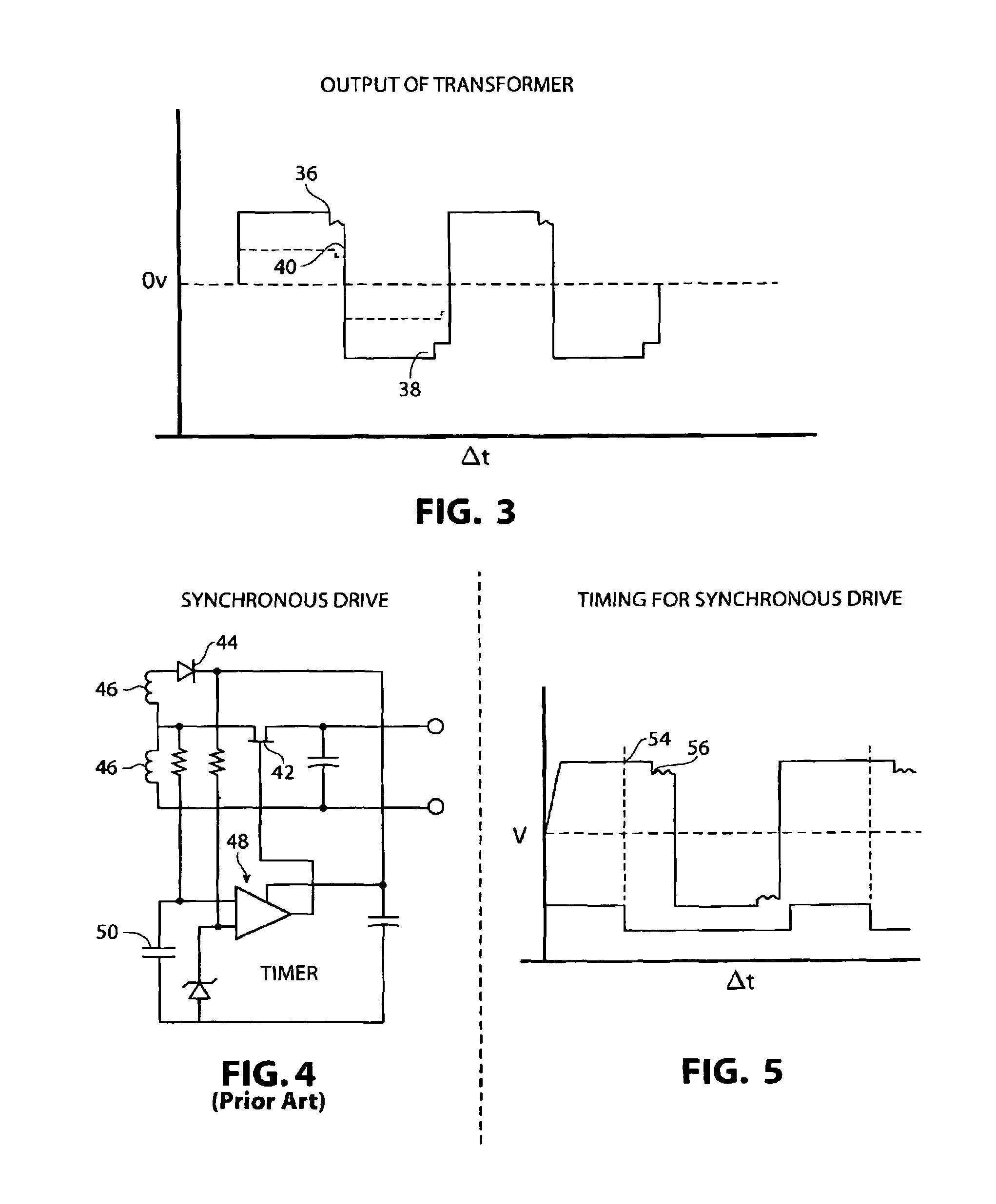
[0041]As previously described, the new invention utilizes a new and novel technique to allow a resonant circuit to remain in a synchronized state, regardless of the fact that there is only one transformer, and regardless of the fact that the reflected leakage inductance is varying by an order of over two to one. This is accomplished by utilizing a new technique called trailing edge modulation.

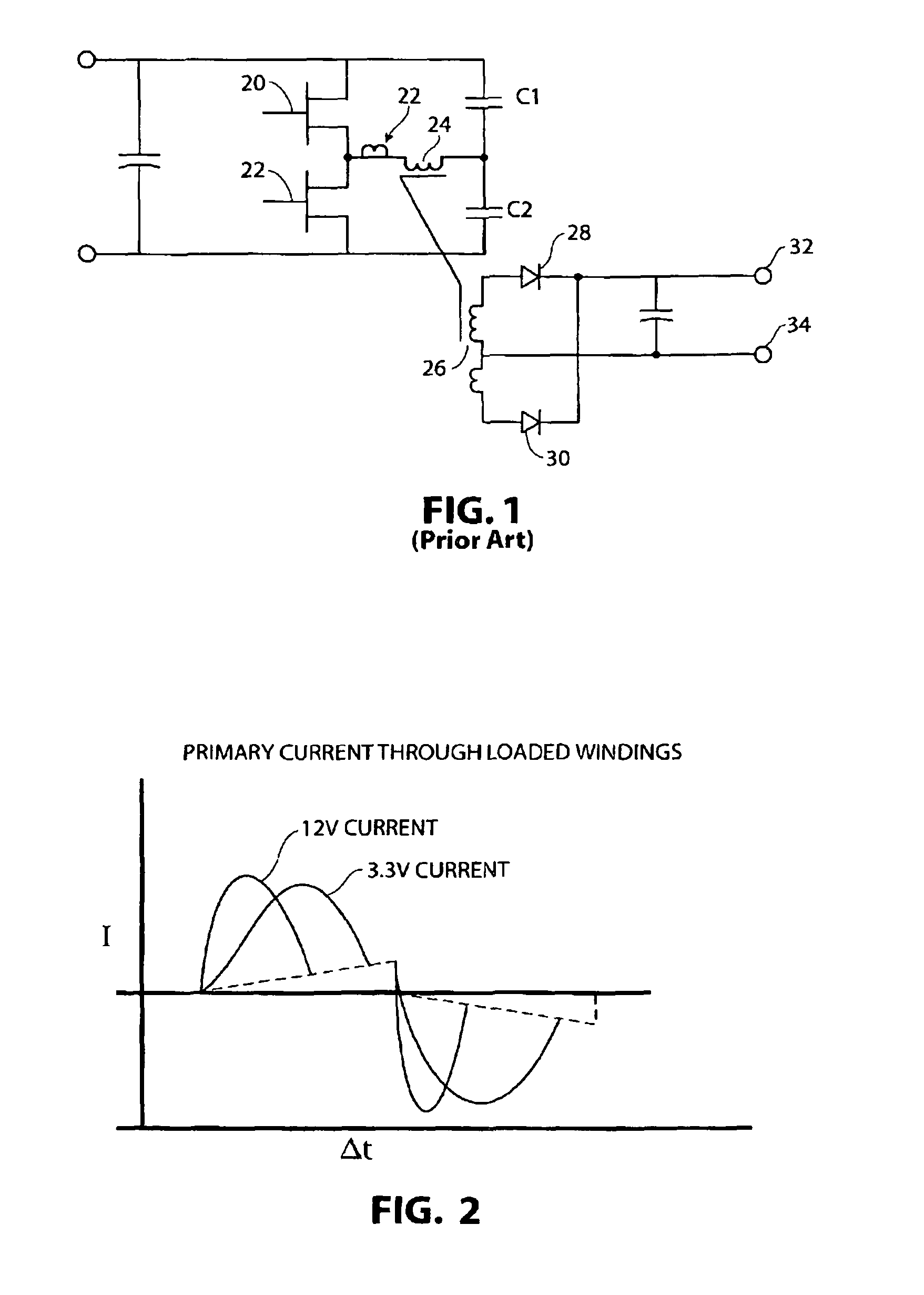
[0042]In this new trailing edge modulation technique, each of the outputs, e.g., the 3.3 Volts, the 5 Volts, or the 12 Volts has a circuit that terminates the operation of the synchronous field effect transistors (Fet's), when the current in the synchronous field effect transistor begins to turn negative, regardless of the load. This means that the cross-load can be any combination, heavy 3.3 and light 12 Volt, or heavy 12 Volt and light 3.3 Volt. Still, the primary current remains a composite sine wave made up of each independent frequency reflected from the secondary, thus remaining in regula...


PUM


Abstract

A resonant DC to DC converter circuit receiving an input voltage and capable of delivering multiple output voltages, while maintaining excellent cross-regulation with only one power transformer. The circuit of the invention uses trailing edge modulation, along with a new amplitude modulation arrangement which allows for the use of resonance with synchronous rectification and only a single power transformer. Thus, the circuit provides for DC to DC conversion, as well as an amplitude modulation arrangement.

Description

RELATED APPLICATION[0001]This application is based on and claims for priority the filing date of my U.S. Provisional Patent Application Ser. No. 60 / 727,085, filed Oct. 13, 2005, for Multiple Voltage DC to DC Resonant Converter, the full contents of which are incorporated herein by reference.BACKGROUND OF THE INVENTION[0002]1. Field of the Invention[0003]This invention relates in general to certain new and useful improvements in circuit arrangements for providing multiple output voltages from a single input voltage, with only a single power transformer, as well as a circuit arrangement which uses trailing edge modulation for providing amplitude modulation and, again, only with a single power transformer. The circuit more preferably provides the amplitude modulation with resonant synchronous rectification using this single power transformer. Specifically, the converter circuit is used in combination with the amplitude modulation circuit arrangement to provide a single DC to DC convert...

Claims


Application Information

Patent Timeline
Patent Type & Authority Patents(United States)
IPC IPC(8): H02M7/217H02M3/335
CPCH02M3/33561Y02B70/1433Y02B70/10Y02P80/10
Inventor ARCHER, MICHAEL
Owner ERP POWER
Why Eureka
Try Eureka