Compression ignition internal combustion engine, glow plug, and injector
a technology of compression ignition and internal combustion engine, which is applied in the direction of combustion air/fuel air treatment, electric control, lighting and heating apparatus, etc., can solve the problems of preventing its widespread use, affecting the original advantages of internal combustion engine in which combustion reaction is initiated by self-ignition, and high cost of common rail system as such, so as to achieve the effect of easy detachment, low cost, and easy detachmen
- Summary
- Abstract
- Description
- Claims
- Application Information
AI Technical Summary
Benefits of technology
Problems solved by technology
Method used
Image
Examples
first embodiment
[0086](First Embodiment)
[0087]In the present embodiment, the fuel contains a hydrocarbon compound, and the gas provided to the reaction with fuel is air. The gas reacts with fuel as an oxidizing gas or combustion-supporting gas, and combustion is achieved as a result.
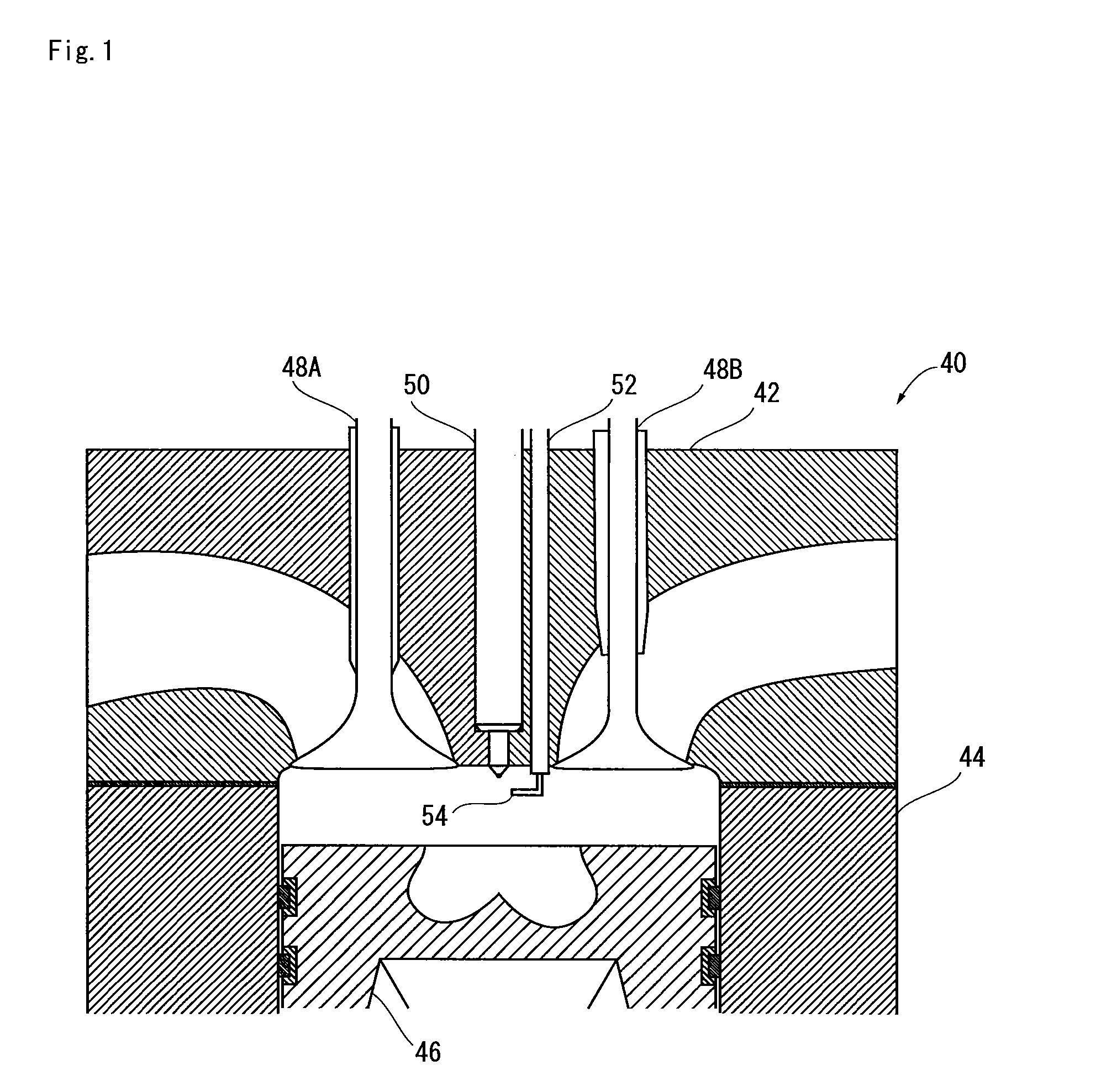
[0088]FIG. 1 shows the internal composition of a diesel engine 40 as an example of a compression-ignition internal combustion engine in which the method form improving combustion according to the present embodiment is implemented.
[0089]The diesel engine 40 has a cylinder head 42, a tubular cylinder liner 44 joined to the cylinder head 42, and a piston 46 that makes sliding contact with the cylinder liner 44, as shown in FIG. 1. The space enclosed by these members is a combustion chamber.
[0090]An intake port and an exhaust port are provided to the cylinder head 42, and valves 48A, 48B that can be opened and closed are arranged facing the combustion chamber in the boundary area between the combustion chamber and the intak...
second embodiment
[0119](Second Embodiment)
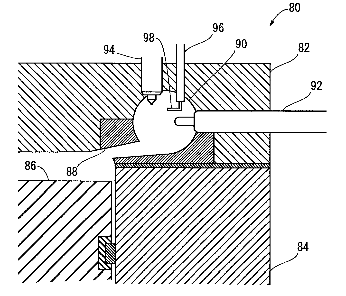
[0120]The diesel engine 80 shown in FIG. 5 is a so-called subsidiary combustion chamber engine. The diesel engine 80 has a cylinder head 82, a cylinder liner 84, and a piston 86 that makes sliding contact with the cylinder liner 84, as shown in FIG. 5. A recess is provided in the cylinder head 82 in a position facing the piston.
[0121]The diesel engine 80 furthermore has a chamber collar 88 fitted onto the piston-side portion of the recess. A through-hole that passes from the remaining portion of the recess of the cylinder head 82 to the space facing the piston (i.e., the combustion chamber) is provided to the chamber collar 88. A swirl chamber 90 is formed by the portion on which the chamber collar 88 is not fitted around the recess of the cylinder head and by a portion of the through-hole in the chamber collar.
[0122]Three through-holes that pass from the swirl chamber 90 to a space outside the combustion chamber are formed in the cylinder head 82, and a glo...
third embodiment
[0129](Third Embodiment)
[0130]In the second embodiment and the modification of the second embodiment, the composition had a microwave transmission channel and an antenna disposed in the cylinder head, but the present invention is not limited to such a composition. An embodiment of a glow plug provided with a microwave transmission channel and an antenna is described hereinbelow.
[0131]FIG. 6 shows the composition of the glow plug 100 of the present embodiment. The glow plug 100 is a so-called red-hot coil-type glow plug, as shown in FIG. 6. The glow plug 100 has a terminal 102 to which power is fed for heating, a cap 104 joined to the terminal 102, a cylindrical case 106 joined to the cap 104, a connector 108 for accommodating a conductor (not shown) connected to the terminal 102 through the cap 104, a conductor power feed wire 110 connected to the connector 108, and a resistance wire 112 provided to the side opposite from the connector 108 of the power feed wire 110.
[0132]In the glo...
PUM
 Abstract
Description
Claims
Application Information
 - R&D
- Intellectual Property
- Life Sciences
- Materials
- Tech Scout
- Unparalleled Data Quality
- Higher Quality Content
- 60% Fewer Hallucinations
Browse by: Latest US Patents, China's latest patents, Technical Efficacy Thesaurus, Application Domain, Technology Topic, Popular Technical Reports.
© 2025 PatSnap. All rights reserved.Legal|Privacy policy|Modern Slavery Act Transparency Statement|Sitemap|About US| Contact US: help@patsnap.com


