Compression ignition internal combustion engine, glow plug, and injector

Inactive Publication Date: 2010-08-05
MAGINEERING INC
View PDF6 Cites 35 Cited by
  • Summary
  • Abstract
  • Description
  • Claims
  • Application Information

AI Technical Summary

Benefits of technology

[0064]In accordance with the twenty-third aspect, it is possible to readily achieve the effects of the first to twenty-second aspects at low cost in a conventional compression-ignition internal combustion engine by integrating an antenna and a readily detachable glow plug in the combustion chamber.
[0065]In accordance with the twenty-fourth aspect, it is possible to readily arrange an antenna at low cast in a suitable position, and to achieve the effects of the first to twenty-second aspects in a conventional compression-ignition internal combustion engine by integrating an antenna and a readily detachable injector in the combustion chamber.
[0066]As described above, in accordance with the present invention, electromagnetic wave emission and the formation of plasma in conjunction with the electromagnetic wave emission make it possible to obtain the same effects as the effect of improved mixing brought about by faster fuel injection, the effect of reduced ignition delay time, and the effect of reduced combustion time. In other words, the present invention can yield the same operation and effect as the common rail system while reducing the valve-opening pressure in a fuel injection mechanism. This contributes to a simplification of the structure of the fuel injection mechanism.
[0067]In accordance with the present invention, electromagnetic wave emission

Problems solved by technology

For this reason, a common rail system as such is costly, which prevents its widespread use.
Such an engine cannot be referred to as a compression-ignition inter

Method used


Image

  • Compression ignition internal combustion engine, glow plug, and injector
  • Compression ignition internal combustion engine, glow plug, and injector
  • Compression ignition internal combustion engine, glow plug, and injector

Examples


Example

[0086]First Embodiment

[0087]In the present embodiment, the fuel contains a hydrocarbon compound, and the gas provided to the reaction with fuel is air. The gas reacts with fuel as an oxidizing gas or combustion-supporting gas, and combustion is achieved as a result.

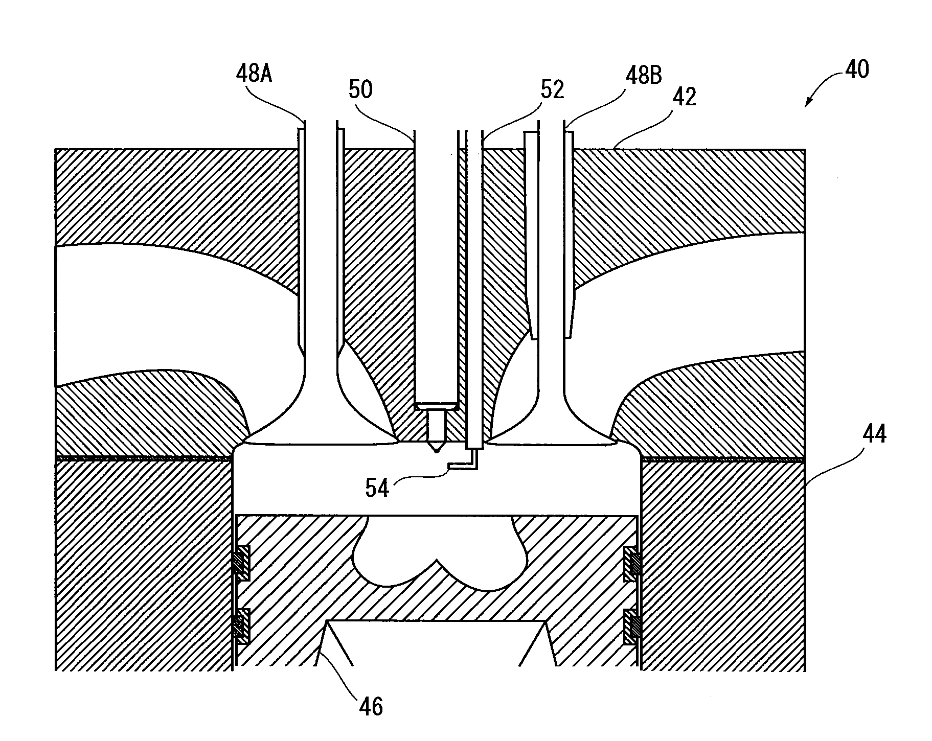
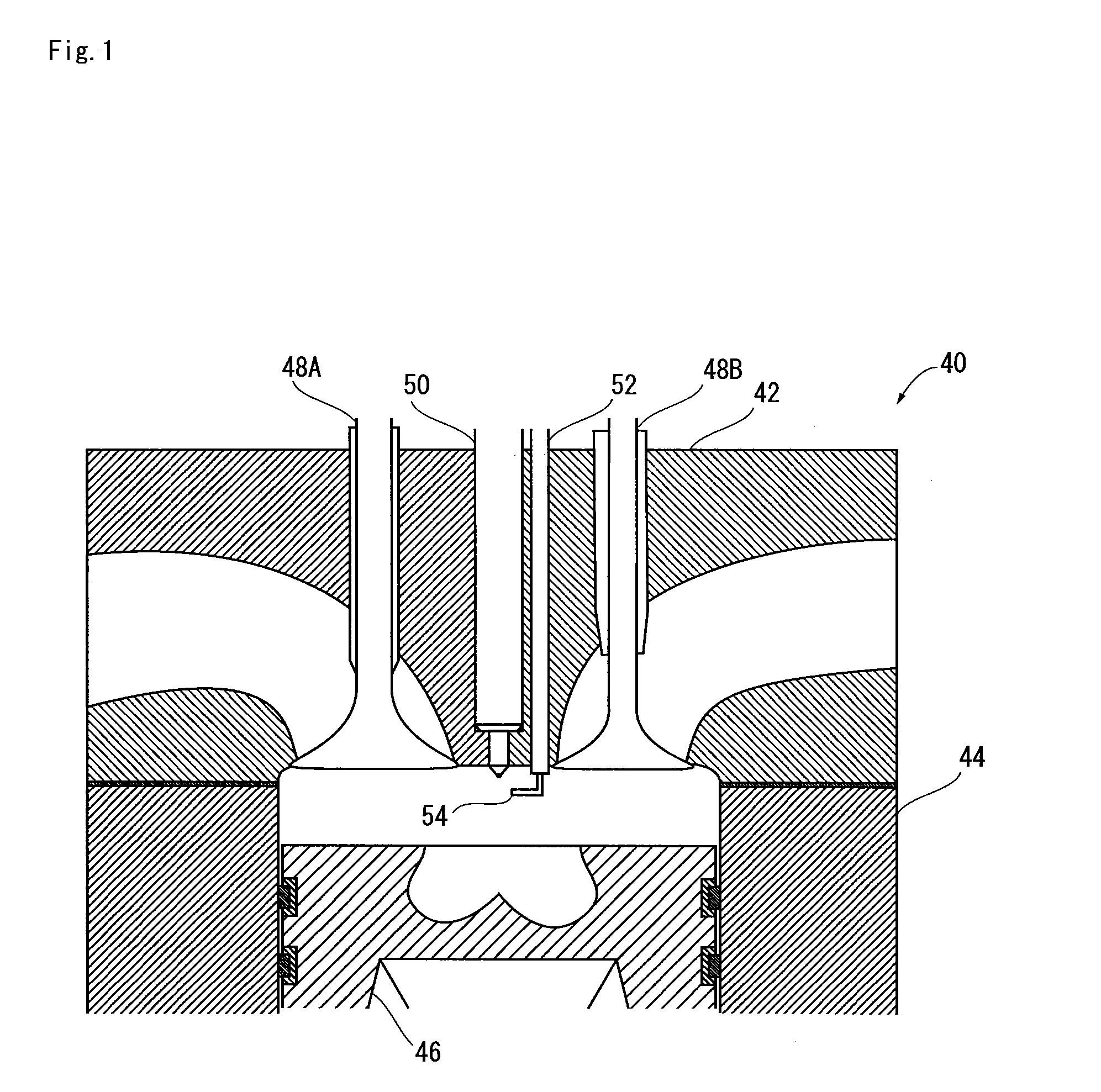
[0088]FIG. 1 shows the internal composition of a diesel engine 40 as an example of a compression-ignition internal combustion engine in which the method form improving combustion according to the present embodiment is implemented.

[0089]The diesel engine 40 has a cylinder head 42, a tubular cylinder liner 44 joined to the cylinder head 42, and a piston 46 that makes sliding contact with the cylinder liner 44, as shown in FIG. 1. The space enclosed by these members is a combustion chamber.

[0090]An intake port and an exhaust port are provided to the cylinder head 42, and valves 48A, 48B that can be opened and closed are arranged facing the combustion chamber in the boundary area between the combustion chamber and the intake ...

Example

[0119]Second Embodiment

[0120]The diesel engine 80 shown in FIG. 5 is a so-called subsidiary combustion chamber engine. The diesel engine 80 has a cylinder head 82, a cylinder liner 84, and a piston 86 that makes sliding contact with the cylinder liner 84, as shown in FIG. 5. A recess is provided in the cylinder head 82 in a position facing the piston.

[0121]The diesel engine 80 furthermore has a chamber collar 88 fitted onto the piston-side portion of the recess. A through-hole that passes from the remaining portion of the recess of the cylinder head 82 to the space facing the piston (i.e., the combustion chamber) is provided to the chamber collar 88. A swirl chamber 90 is formed by the portion on which the chamber collar 88 is not fitted around the recess of the cylinder head and by a portion of the through-hole in the chamber collar.

[0122]Three through-holes that pass from the swirl chamber 90 to a space outside the combustion chamber are formed in the cylinder head 82, and a glow ...

Example

[0129]Third Embodiment

[0130]In the second embodiment and the modification of the second embodiment, the composition had a microwave transmission channel and an antenna disposed in the cylinder head, but the present invention is not limited to such a composition. An embodiment of a glow plug provided with a microwave transmission channel and an antenna is described hereinbelow.

[0131]FIG. 6 shows the composition of the glow plug 100 of the present embodiment. The glow plug 100 is a so-called red-hot coil-type glow plug, as shown inFIG. 6. The glow plug 100 has a terminal 102 to which power is fed for heating, a cap 104 joined to the terminal 102, a cylindrical case 106 joined to the cap 104, a connector 108 for accommodating a conductor (not shown) connected to the terminal 102 through the cap 104, a conductor power feed wire 110 connected to the connector 108, and a resistance wire 112 provided to the side opposite from the connector 108 of the power feed wire 110.

[0132]In the glow p...


PUM


Abstract

The invention provides a practical diesel engine that uses plasma formed by microwave emissions. In a compression-ignition internal combustion engine, fuel is sprayed by an injector in the combustion chamber in which compressed oxidizing gas is present, and the fuel is compressed and ignited. The engine has one antenna or a plurality of antennas in the combustion chamber, and when the oxidizing gas or moisture and charged particles are present in the combustion chamber, an electromagnetic wave is emitted using the antenna in a space in which the oxidizing gas and the charged particles are present, and plasma is generated in the space by the energy fed to the charged particles.

Description

TECHNICAL FIELD[0001]The disclosure relates to a diesel engine or another compression-ignition internal combustion engine in which compression is improved using plasma, and to a glow plug and injector therefor.BACKGROUND OF THE INVENTION[0002]Compression-ignition internal combustion engines typified by diesel engines are internal combustion engines in which air or another gas to be reacted with fuel is highly compressed, fuel is introduced into the high-temperature, high-pressure atmosphere, the fuel is dispersed to form a so-called mixture, and the mixture is made to self-ignite. Since the compression-ignition internal combustion engine can, in theory, use various types of fuel, the value of such engines as low-pollution engines is being reassessed. However, there is a problem in a diesel engine in that substances that cause air pollution are generated in large quantities when combustion is not carried out in optimal conditions. For example, the combustion reaction is incomplete wh...

Claims


Application Information

Patent Timeline
IPC IPC(8): F02D41/04F02B51/04
CPCF02B3/06F02D41/402F02B23/0657F02B23/0669F02B23/0672F02B2275/14F02M27/042F02M27/08F02P15/006F02P15/02F02P19/02F02P23/045F23Q7/001Y02T10/125Y02T10/123Y02T10/166Y02T10/44F02B19/14Y02T10/12Y02T10/40
Inventor IKEDA, YUJI
Owner MAGINEERING INC
Why Eureka
Try Eureka