Memory module cutting off DM pad leakage current

Active Publication Date: 2012-04-17
SAMSUNG ELECTRONICS CO LTD
View PDF8 Cites 4 Cited by
  • Summary
  • Abstract
  • Description
  • Claims
  • Application Information

AI Technical Summary

Benefits of technology

[0013]Embodiments of the inventive concept provide a memory module for incorporatio

Problems solved by technology

In its operation, the DRAM may be characterized as a volatile memory device since stored data is lost i

Method used


Image

  • Memory module cutting off DM pad leakage current
  • Memory module cutting off DM pad leakage current
  • Memory module cutting off DM pad leakage current

Examples


Embodiment Construction

[0024]Embodiments of the inventive concept will now be described more fully with reference to the accompanying drawings. However, it should be noted that the inventive concept may be variously embodied and should not be construed as being limited to only the illustrated embodiments.

[0025]Specific structural and functional details disclosed herein are merely representative for purposes of describing the illustrated embodiments. Accordingly, the illustrated embodiments are susceptible to various modifications and alternative implementations. It should be understood, however, that there is no intent to limit the scope of the inventive concept to only the illustrated embodiments in their particular forms. Rather, the inventive concept is intended to cover all modifications, equivalents, and alternatives falling within the scope of following claims. Throughout the written description and drawings, like reference numbers refer to like or similar elements.

[0026]It will be understood that, ...


PUM


Abstract

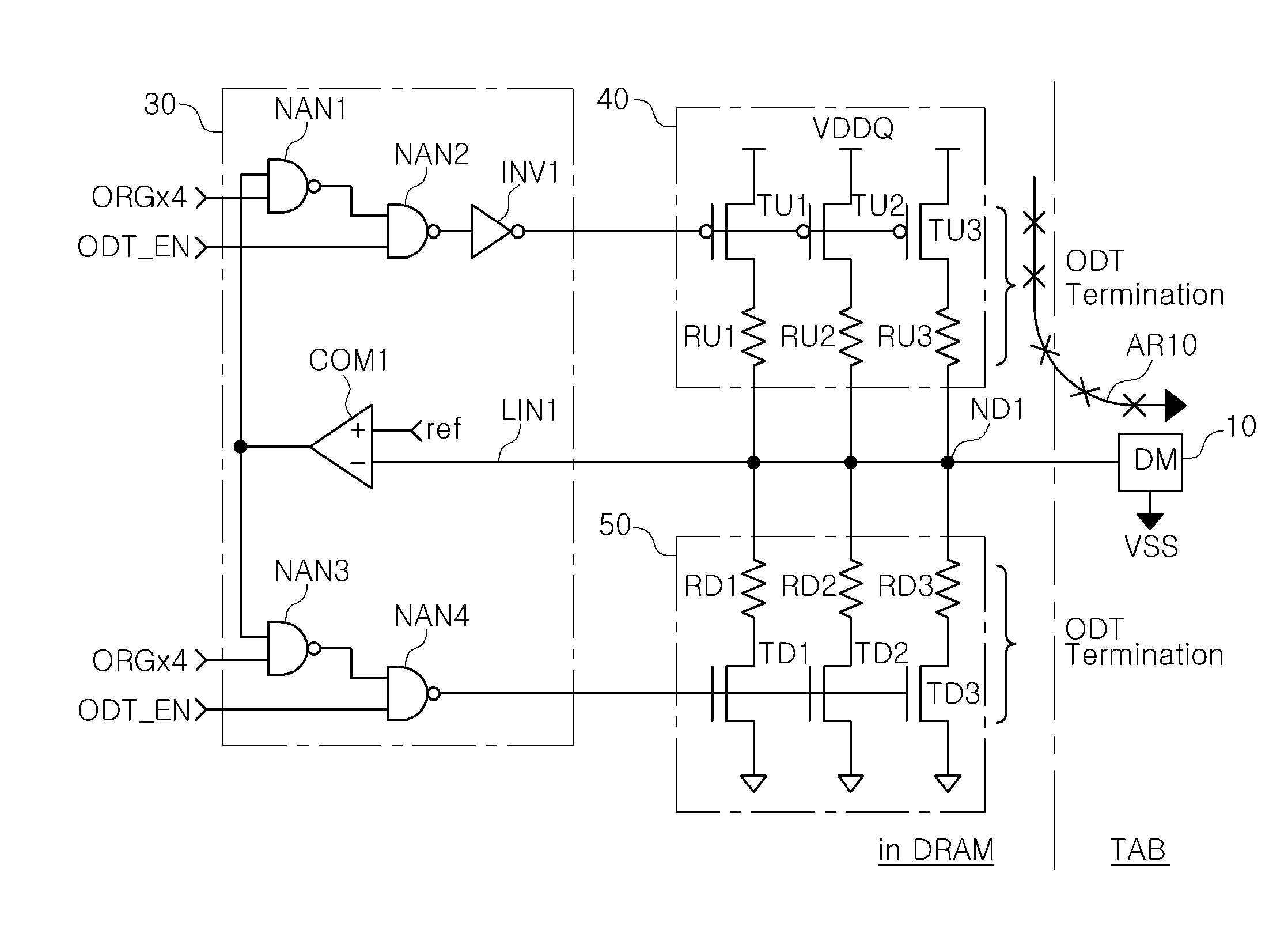
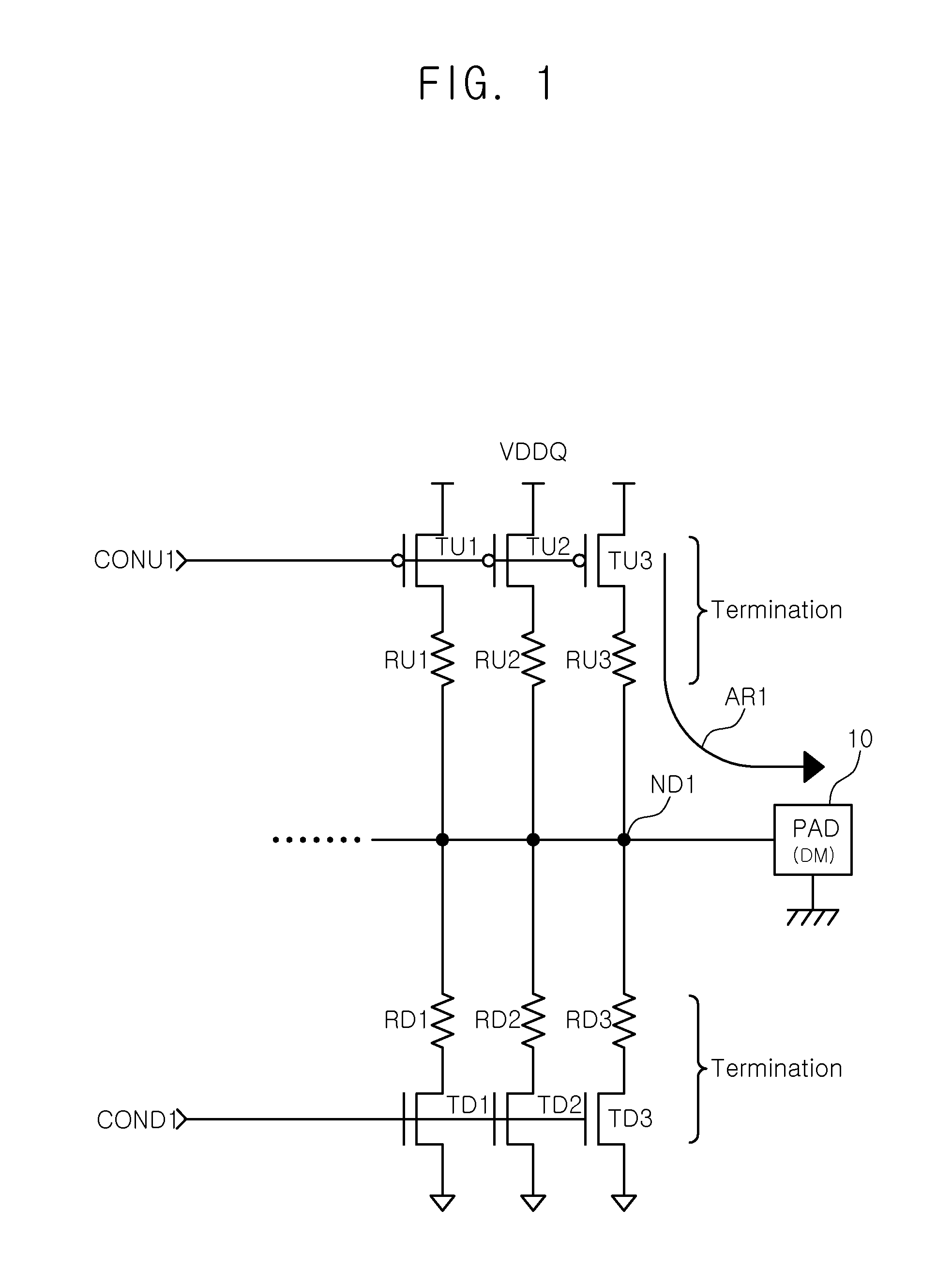
A memory module includes: an ODT circuit on a memory device and including pull-up and pull-down resistors connected between pull-up and pull-down transistors. A data masking (DM) pad is provided in a tap region of the module board. A current leakage monitoring unit is also provided and receives a ground state signal from the DM pad and a bit configuration signal from the memory device and disables the pull-up transistors to cut off a current path between the pull-up resistors of the ODT circuit and the DM pad during a ODT enable mode.

Description

CROSS-REFERENCE TO RELATED APPLICATION[0001]This U.S. non-provisional patent application claims the benefit of Korean Patent Application 10-2009-0010474 filed on Feb. 10, 2009, the subject matter of which is hereby incorporated by reference.BACKGROUND[0002]The present inventive concept relates to memory modules, such as those commonly used in data processing apparatuses. More particularly, the inventive concept relates to memory modules capable of cutting off leakage current.[0003]Various semiconductor devices, such as CPUs, memories, and gate arrays, implemented by integrated circuit chips are incorporated into various data processing apparatuses, such as portable personal computers, PDAs, servers, and workstations. These data processing apparatuses may be capable of operating in a sleep mode during which most of the internal circuitry is placed in a standby state in order to reduce power consumption.[0004]Many main memories for data processing apparatuses are implemented with semi...

Claims


Application Information

Patent Timeline
IPC IPC(8): G11C5/02
CPCG11C5/06G11C7/1078G11C7/1084G11C11/4093G11C2207/105G11C7/10G11C7/24
Inventor KIM, SEOK-ILHAN, YOU-KEUNSEO, SEUNG-JIN
Owner SAMSUNG ELECTRONICS CO LTD
Why Eureka
Try Eureka