Ultrasonic sensor
a technology of ultrasonic sensor and acoustic matching member, which is applied in the direction of instruments, heat measurement, specific gravity measurement, etc., can solve the problems of difficult placement of microballons inside the acoustic matching member, and difficulty in accurately detecting humidity, so as to prevent a reduction in transmitting and receiving sensitivities
- Summary
- Abstract
- Description
- Claims
- Application Information
AI Technical Summary
Benefits of technology
Problems solved by technology
Method used
Image
Examples
first embodiment
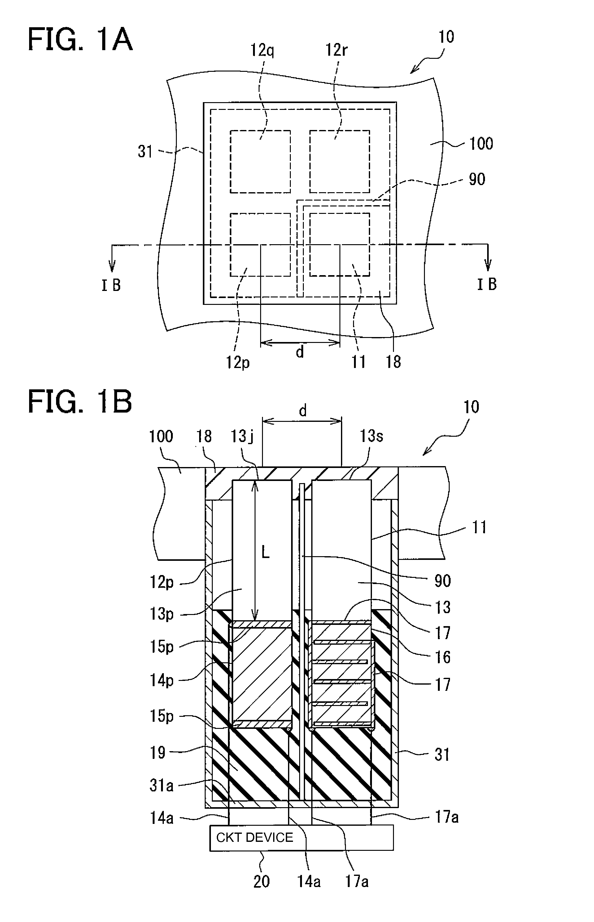
[0025]An ultrasonic sensor 10 according to a first embodiment of the present invention is described below with reference to FIGS. 1A and 1B. For example, the ultrasonic sensor 10 can be used as an obstacle sensor mounted on a vehicle. The lower side of FIG. 1A is directed to the ground, and the upper side of FIG. 2 is directed to an outside of the vehicle.
[0026]The ultrasonic sensor 10 includes a transmitting device 11, receiving devices 12p, 12q, 12r, a vibration damper 18, a first absorber 19, a vibration isolator 90, a circuit device 20, and a housing 31. The transmitting device 11 transmits an ultrasonic wave. The receiving devices 12p, 12q, 12r detect the ultrasonic wave reflected from an object (i.e., obstacle) to be detected. The vibration damper 18 prevents propagation of the ultrasonic wave among the transmitting device 11 and the receiving devices 12p, 12q, and 12r. The first absorber 19 protects the transmitting device 11 and the receiving devices 12p, 12q, and 12r from e...
second embodiment
[0087]An ultrasonic sensor 110 according to a second embodiment of the present invention is described below with reference to FIGS. 5 and 6. A difference between the first and second embodiments is as follows.
[0088]The ultrasonic sensor 110 further includes a pair of electrodes 41 used to detect a dielectric constant of the first absorber 19. A circuit device 20 of the ultrasonic sensor 110 performs a threshold adjustment process illustrated in FIG. 6 instead of the threshold adjustment process illustrated in FIGS. 3 and 4.
[0089]As shown in FIG. 5, the electrodes 41 are embedded in the first absorber 19 and spaced from each other. The electrodes 41 are electrically connected to the circuit device 20 through wires 41a, respectively. The circuit device 20 detects the dielectric constant of the first absorber 19 based on a capacitance between the electrodes 41.
[0090]The threshold adjustment process performed by the circuit device 20 of the ultrasonic sensor 110 is described below with ...
third embodiment
[0094]An ultrasonic sensor 210 according to a third embodiment of the present invention is described below with reference to FIG. 7. A difference between the second and the third embodiments is as follows.
[0095]The ultrasonic sensor 210 includes a surface acoustic wave (SAW) element 50 instead of the electrodes 41 of the ultrasonic sensor 110.
[0096]The SAW element 50 includes electrodes 51, 52. As can be seen from FIG. 7, each of the electrodes 51, 52 has a comb shape and attached on a surface of the piezoelectric element 14p. It is noted that the piezoelectric element 14p of FIG. 7 is not a cross-sectional view for explanation purpose. The electrodes 51, 52 are spaced from each other and electrically connected to the circuit device 20 through wires (not shown), respectively.
[0097]The SAW element 50 receives a control signal from the circuit device 20 and causes the electrode 51 to emit a surface acoustic wave of a predetermined frequency according to the control signal. The emitted...
PUM
| Property | Measurement | Unit |
|---|---|---|
| thickness | aaaaa | aaaaa |
| resonance frequency Fc | aaaaa | aaaaa |
| round-trip distance | aaaaa | aaaaa |
Abstract
Description
Claims
Application Information
 - R&D
- Intellectual Property
- Life Sciences
- Materials
- Tech Scout
- Unparalleled Data Quality
- Higher Quality Content
- 60% Fewer Hallucinations
Browse by: Latest US Patents, China's latest patents, Technical Efficacy Thesaurus, Application Domain, Technology Topic, Popular Technical Reports.
© 2025 PatSnap. All rights reserved.Legal|Privacy policy|Modern Slavery Act Transparency Statement|Sitemap|About US| Contact US: help@patsnap.com


