Three-wheel, driver's stand-up, portable, leverless vehicle, with foot brake lever and connecting method thereoff

a personal mobility and electric technology, applied in the direction of folding cycles, propulsion by batteries/cells, cycles, etc., can solve the problems of not being able to maintain extreme balance and control, not being able to drive fast, and not being able to facilitate extreme balance and control for many people, etc., to achieve simple electrical connection and extreme control

Active Publication Date: 2012-05-01
TSIYONI JOSEPH
View PDF26 Cites 38 Cited by
  • Summary
  • Abstract
  • Description
  • Claims
  • Application Information

AI Technical Summary

Benefits of technology

[0118]With respect the brake (pedal) lever, note that while this invention cited using a brake food (pedal) lever probably the first time in PMV's, it should be indicated that “foot pedal” was claimed in a different aspect in U.S. Pat. No. 6,343,667. There, it is introduced in a different connotation, methods and usage, especially comparing to the ‘old’, traditional pedals and concept, referring to a brake or a clutch foot pedal. As much as this patent was granted, also for introducing a foot pedal while the concept of foot pedal, as cited for vehicle is that old, so introducing a foot lever in the concept and means introduced in this invention worthwhile such consideration as an improvement with merits. In said cited patent, the ‘pedal’ is simply a large, bull type, round means installed on the frame, whereby the driver depresses it to turn the motor on. Note that these types of scooters are normally skateboards types with battery-powered electric motors, which are fast, request extreme control, and probably some bravery to drive so fast. These are not in the area of the present invention, and absolutely not for the use by the type of population cited in this application for this new invention.
[0119]With respect to the electrical assembly, the invention presented here provides a simple, ages old and known concept of outlet-plug connection, which is applied here for many reasons, including simplicity, efficiency and productivity. This would be response to another invention filed under US PUB No. 2008-0261435. There, a complicated electric connection guide assembly was introduced to resolve numerous complicated electrical issues involving brakes, electrical motors power supply components, whereby the entire patent was devoted to that matter.
[0120]While said patent did resolve some important electrical connection via the assembly provided, here, in this present invention, the electrical connection is simple, and, in general out of the scope of said patent cited here.
[0121]Therefore, the electrical connection used in this present invention has been in use for years in many electric PMV's. Therefore, as previously stated, while this patent is solely for electric assembly, the electric connection provided in the present invention is one of many features presented in one invention.
[0122]The above summary, which broadly presented the new invention in comparison to prior art, and its significant advantages, makes it obvious to understand the manner in which this new innovative and novel PMV operates. However, to make it extremely clearer, and to show the practical many features involved, the following last section of the summary part demonstrate the practical use, whereby the reader may feel he or she is driving the new vehicle while reading.
[0123]In less than 7 seconds, the driver holds the banana-shape leg of the front wheel assembly, (which is raised above the grand due manufacturing assembly); then the driver slightly lifts and aligns the end tube (sleeve) mounted at the end of the second part of the telescope mounted on the platform, and inserts the former tube inside the latter tube formed on the platform part. Then the driver stands on the platform, and using the throttle, starts driving.

Problems solved by technology

In addition, millions others have limited prolong walk or total inability to walk, due to other, numerous, medical conditions.
These people are excluded from the group of users of this new invention, because they will not be able to use it due to sever medical condition and disability.
However, those high speed PMV's do not make it possible for many people to maintain extreme balance and control, nor enabling driving fast.
Note that the most common used electric personal transporter for those people with total inability to walk, or with prolong walk limitation, is known as an “electric scooter” or “electric wheelchair”, AKA, PMV, normally a three-wheel vehicle, extremely heavy, relatively inflexible, and complicated to handle.
In further developments and added features related to the prior art, several patents were issued for features of other PMV's, which, despite the patents granted, simply show more disadvantages, such as portable heavy PMV's (mostly related to PMV's used by people confined to wheelchair (when used), who need to use electric PMV's for transportation, and also need to load and unload such PMV's to places such as a trunk of a vehicle, a buss, an airplane, ramps and trucks.
Nevertheless, all of these scooters (or personal mobility vehicles) are heavy, cannot be disassembled and assembled, and even if some do, as cited here, each part is very heavy, complicated, and makes the transfer of the scooter onto a car trunk or any other place impossible by one person, especially that those PMV's are made and intended for people with disability.
Those people are not aware of the existence of such vehicle, thereby they are not able to enjoy its efficiency, and make their livelihood much better.

Method used


Image

  • Three-wheel, driver's stand-up, portable, leverless vehicle, with foot brake lever and connecting method thereoff
  • Three-wheel, driver's stand-up, portable, leverless vehicle, with foot brake lever and connecting method thereoff
  • Three-wheel, driver's stand-up, portable, leverless vehicle, with foot brake lever and connecting method thereoff

Examples


Embodiment Construction

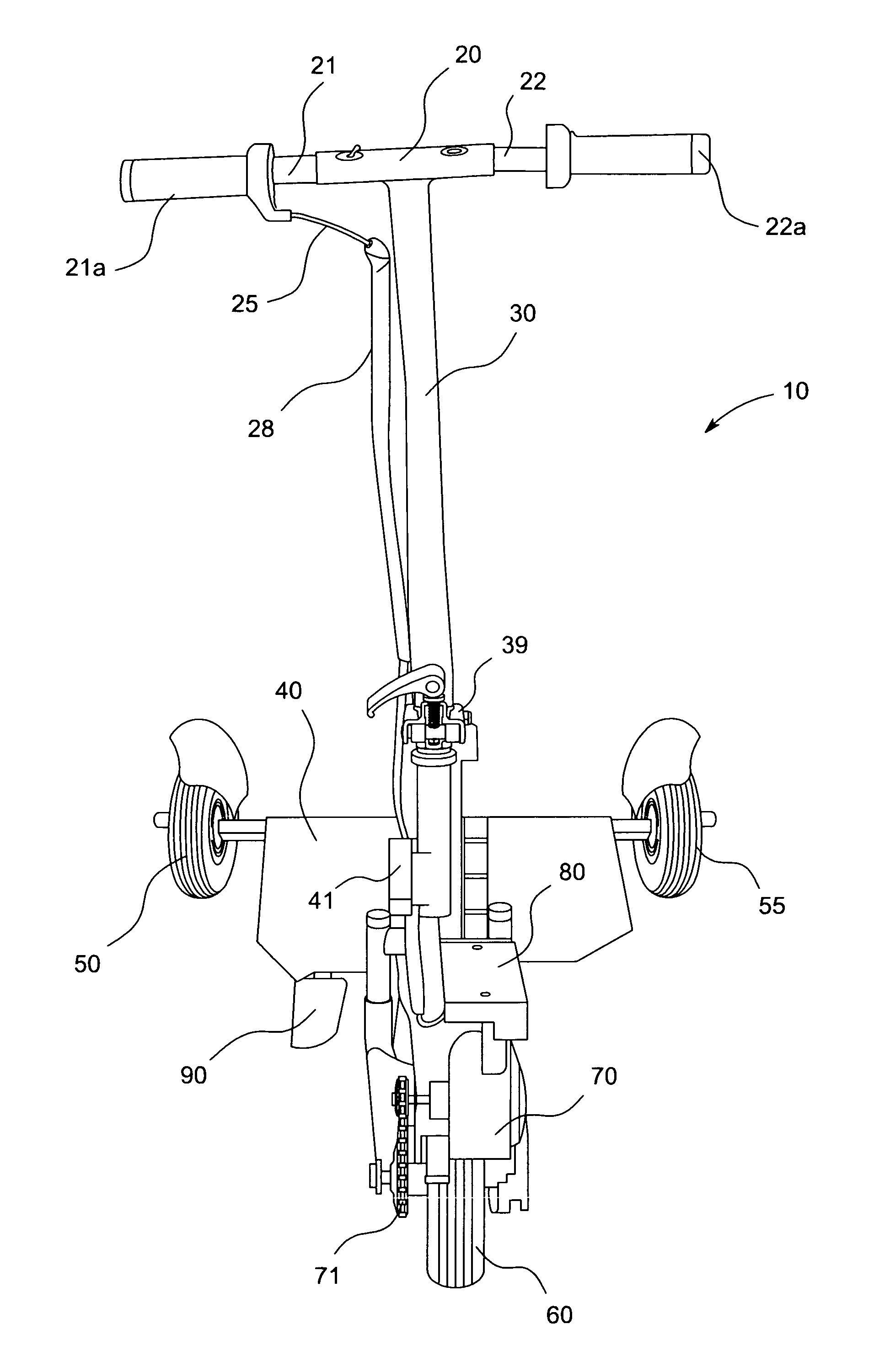
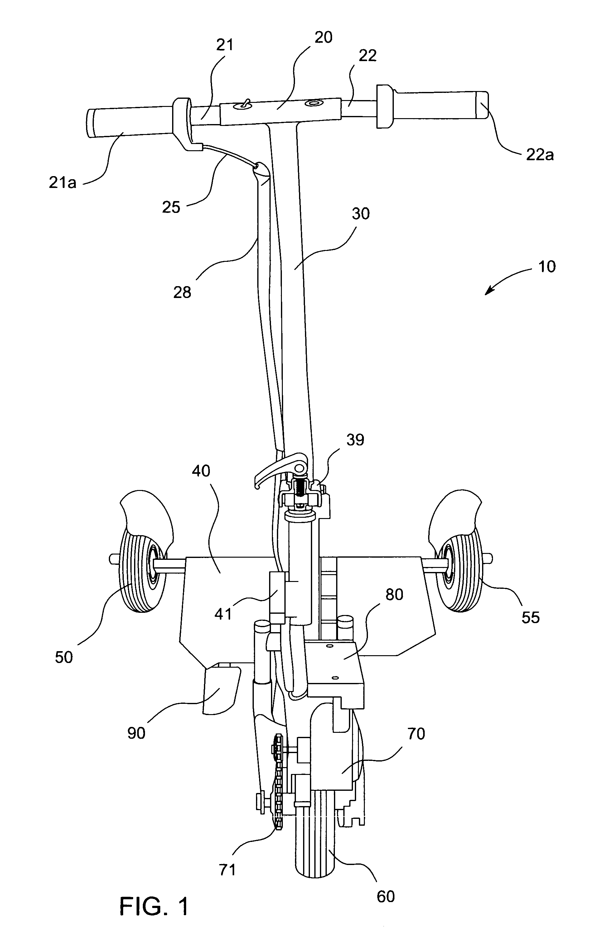
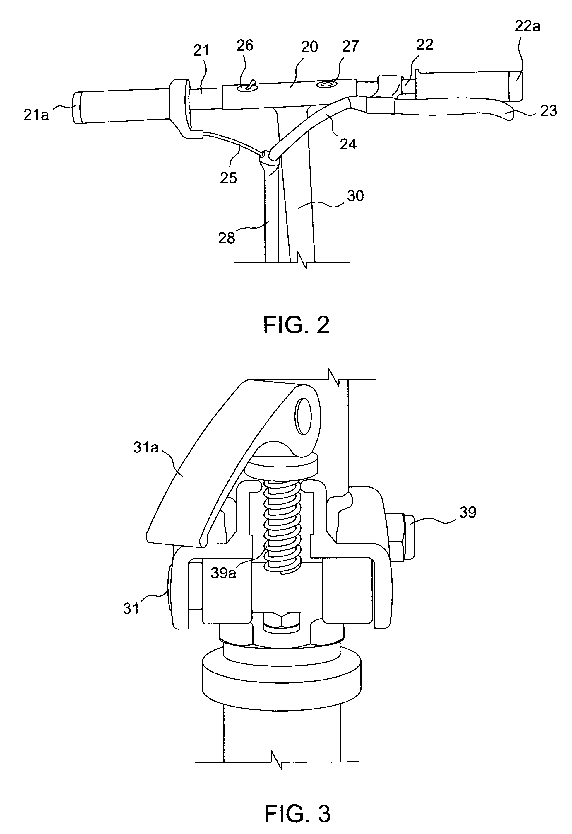
[0162]This new and improved invention is a generally portable 3-wheel electric personal transport vehicle (personal transporter vehicle-scooter 10) empowered by a battery, a leverless steering handle, an electric motor, a connecting assembly between the two main parts of the PMV suing a telescope fit concept / mechanism comprises of a receiving and sleeve telescope fit tubes with respective ID / OD, a unique method and mechanism of hydraulic brake assembly operated by a light move of the driver's foot of a brake lever, whereby said PMV can be assembled and disassembled into two or three parts in seconds, whereby the entire PMV, and so each of the three parts are in extremely light weight, which can be carried, together, or separately, by one person, or each by one hand.

More Specifically:

[0163]FIG. 1 is a front perspective view of the electric personal transporter vehicle-scooter 10 of the present invention shows a front perspective view of an electric personal transporter vehicle-scoote...


PUM


Abstract

A slow speed, driver's stand-up only, three-wheels, portable, leverless, extremely lightweight, two-part personal mobility vehicle. A front major part, wheel drive assembly, comprising of an upper sub-part, comprising of levers free steering handle mounted on steering column. A lower sub-part comprises of an extended backwards supporting leg, a control box, an electric chain motor assembly, a fork assembly, and front wheel assembly. A two-part hinge assembly below the steering column, enabling folding steering column, and, if necessary, removal. A second major part, a rear assembly chassis, comprising of a riders flat platform surface mounted on a rectangular metal frame, partially mounted on a rear axle, which is connected to both rear wheels. A rear hydraulic foot brake system installed in both rear wheels, whereby a foot brake (pedal) lever formed on top platform surface. An alternative, none-emergency hand brake lever, may be fastened on the steering handle. A removable battery pack is formed on the platform surface. A two-part telescopic box fit assembly, whereby a receiving part is mounted upward on the end of extended leg; a second, sleeve-type part, is formed, respectively, downward on the front platform frame, for interconnecting both major vehicle parts into a complete vehicle, ready to drive at lower speed than 5 MPH. Two sets of simple outlet-plug assembly are formed on respective parts of the battery and platform, and on both ends of the telescopic assembly to supply power to the motor. Said telescopic connecting mechanism enables assembly, disassembly, loading and unloading in less than seven seconds.

Description

CROSS-REFERENCE TO RELATED APPLICATION[0001]The current application claims priority to prior filed application Ser. No. 61 / 201,714, entitled Portable Personal Transporter-Scooter, filed Mar. 23, 2009.BACKGROUND OF THE INVENTION[0002]1. Field of the Invention[0003]The present invention relates to vehicles and methods of electric standing personal mobility transporter vehicle for transporting individuals, mostly with prolong walk inability, or total inability to walk, but can stand, and more particularly, to a two-part, compact, lightweight, portable, leverless vehicle and methods of connecting two major parts of the vehicle with a two-part telescopic box fit mechanism, and a rear wheels hydraulic brake system activated by a foot (pedal) lever.[0004]2. The Prior Art[0005]According to a published research, more than seventy million American have prolong walk inability, or total inability to walk, due to numerous medical condition associated with osteoarthritis, disability and for some ...

Claims


Application Information

Patent Timeline
Patent Type & Authority Patents(United States)
IPC IPC(8): B62D61/08B62K15/00
CPCB60T11/04B60T11/08B60T11/10B62K3/002B62K5/025B62K15/00B60L7/26B60L2200/24B60L2250/24B60L2250/26B60L50/20B60L50/66Y02T10/70
Inventor TSIYONI, JOSEPH
Owner TSIYONI JOSEPH
Why Eureka
Try Eureka