Process and apparatus for treating a heavy hydrocarbon feedstock

a technology of hydrocarbon feedstock and processing equipment, which is applied in the direction of sedimentation settling tanks, separation processes, liquid displacement, etc., can solve the problems of difficult removal and difficult ore size, and achieve the effect of reducing turbulence intensity

Active Publication Date: 2012-05-01
SUNCOR ENERGY INC
View PDF214 Cites 12 Cited by
  • Summary
  • Abstract
  • Description
  • Claims
  • Application Information

AI Technical Summary

Benefits of technology

[0010]The feed manifold may include a plurality of adjacently located open channels extending between the inlet and the primary separation container, the open channels being operable to reduce turbulence intensity in the feedstock flow.
[0036]Conditioning the feedstock flow may involve causing the feedstock to flow along a plurality of adjacently located open channels extending between the inlet and the primary separation container, the open channels being operable to reduce turbulence intensity in the feedstock flow.

Problems solved by technology

The ore may also be frozen due to the northerly geographic location of many oil sands deposits, making sizing of the ore more difficult.
For adequate separation of hydrocarbons, the relatively quiescent conditions of the accumulated feedstock may be required in the vessel, which has the adverse effect of allowing neutral density asphaltene mats to accumulate at an interface between the separated hydrocarbon products and the water.
These asphaltene mats accumulate as rag layers and may be difficult to remove.

Method used


Image

  • Process and apparatus for treating a heavy hydrocarbon feedstock
  • Process and apparatus for treating a heavy hydrocarbon feedstock
  • Process and apparatus for treating a heavy hydrocarbon feedstock

Examples


Embodiment Construction

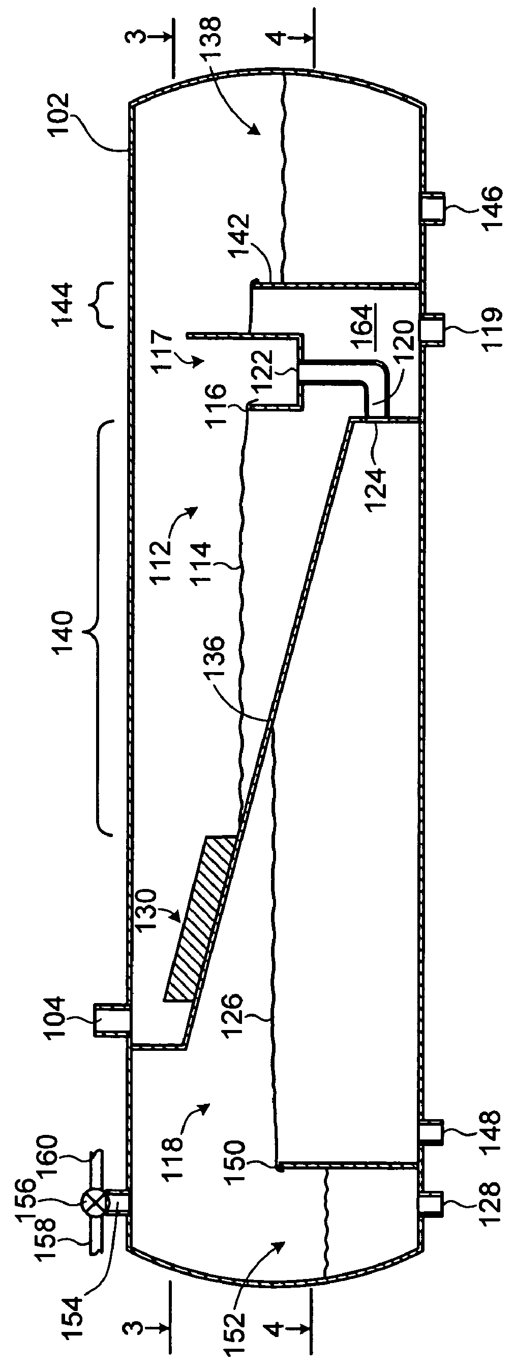
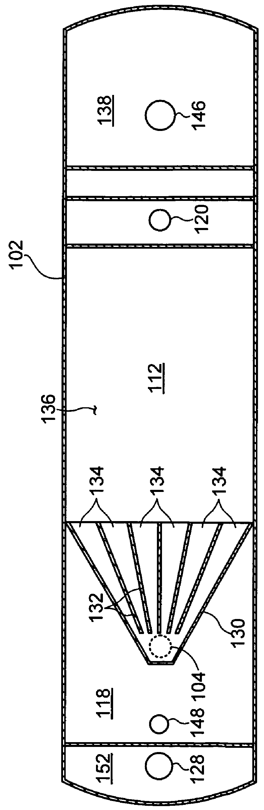
[0068]Referring to FIG. 1, an apparatus for treating a heavy hydrocarbon feedstock according to a first embodiment of the invention is shown generally at 100. The apparatus 100 includes a treatment vessel 102 having an inlet 104 for receiving the feedstock. The feedstock has a specific gravity differential between components of the feedstock.

[0069]In this embodiment the treatment vessel 102 includes a cylindrical portion 106 having first and second dome-shaped end walls 108 and 110. The cylindrical section 104 may be fabricated from a carbon steel pipe section having a wall thickness of about 12 mm. In other embodiments where the feedstock is corrosive, the inside surfaces of the treatment vessel 102 may be treated to resist corrosion or a corrosion resistant metal may be used to fabricate the treatment vessel. In one embodiment the treatment vessel 102 may have a length of about 20 meters and a diameter of about 7 meters. Advantageously, fabrication of the treatment vessel 102 may ...


PUM

PropertyMeasurementUnit
thicknessaaaaaaaaaa
diameteraaaaaaaaaa
lengthaaaaaaaaaa

Abstract

An apparatus and process for treating a heavy hydrocarbon feedstock having a specific gravity differential between components of the feedstock is disclosed. The apparatus includes a treatment vessel having an inlet for receiving the feedstock. The apparatus also includes a primary separation container located in the treatment vessel, the primary separation container being operable to accumulate feedstock to cause a low specific gravity portion of the feedstock to separate and rise to an upper surface of the accumulated feedstock. The apparatus also includes a first weir for collecting the low specific gravity portion from the surface of the accumulated feedstock in the primary separation container. The apparatus further includes a first outlet in the primary separation container, the first outlet being operably configured to receive settling solids in the accumulated feedstock and to produce a first discharge stream at the first outlet. The apparatus also includes a secondary separation container located in the treatment vessel to receive the collected low specific gravity portion, the secondary separation container being operable to accumulate the collected low specific gravity portion to cause hydrocarbon products to separate and rise to an upper surface of the accumulated low specific gravity portion of the feedstock. The apparatus further includes a product outlet for collecting the hydrocarbon products from the upper surface of the accumulated low specific gravity portion to produce a hydrocarbon product stream at the product outlet.

Description

BACKGROUND[0001]1. Field of Invention[0002]This invention relates generally to hydrocarbon extraction and more particularly to a process and apparatus for treating a heavy hydrocarbon feedstock having a specific gravity differential between components of the feedstock.[0003]2. Description of Related Art[0004]Heavy hydrocarbon feedstocks are generally viscous and may be entrained with other components such as rock, sand, clay, and other minerals. As a result, heavy hydrocarbons require processing to separate useful hydrocarbon products from residue before transport and refining.[0005]One example of a heavy hydrocarbon ore deposit is the Northern Alberta oil sands, which comprises about 70 to about 90 percent by weight of mineral solids including sand and clay, about 1 to about 10 percent by weight of water, and a bitumen or oil film. The bitumen may be present in amounts ranging from a trace amount up to as much as 20 percent by weight. Due to the highly viscous nature of bitumen, wh...

Claims


Application Information

Patent Timeline
Patent Type & Authority Patents(United States)
IPC IPC(8): B01D17/028B01D21/02B01D19/00
CPCB01D21/003B01D21/0045B01D21/10B01D21/2494C10G1/00C10G1/047C10G7/00B01D21/0039B01D2221/04C10G2300/206C10G2300/308C10G2300/802
Inventor HANN, THOMAS CHARLES
Owner SUNCOR ENERGY INC
Why Eureka
Try Eureka