Method and apparatus for precision working of material

a material and precision cutting technology, applied in the field of femtosecond laser systems, can solve the problems of unsatisfactory refractive, unsuitable for very fine cut shapes, and not optimal for the above-described application of precision cutting, and achieve the effects of lowering the repetition rate of pulsed work beams, high working precision, and high spot density

Inactive Publication Date: 2012-05-08
CARL ZEISS MEDITEC AG
View PDF20 Cites 47 Cited by
  • Summary
  • Abstract
  • Description
  • Claims
  • Application Information

AI Technical Summary

Benefits of technology

[0012]Therefore, it is the primary object of the present invention to provide an apparatus for precise working of material which overcomes the disadvantages of the prior art.
[0013]In particular, the above-stated object is met by an apparatus for precise working of material, particularly organic material. This apparatus generates cavitation bubbles with a diameter of less than 10 μm in the material to be worked. In order to achieve this, a pulsed laser beam with a pulse energy of less than 5 μJ is focused on a focus diameter of a few micrometers. The focus diameter is preferably about 3 μm and the pulse energy is preferably 1 μJ. Further, the apparatus is characterized in that it permits very fast working through the use of a pulse repetition rate of greater than 50 kHz. This is a great advantage particularly for refractive cornea surgery because an operating time of a few seconds to about 1 minute is achieved in this way.

Problems solved by technology

While these laser sources are suitable for applications with high ablation rates per laser pulse, they are not optimal for the above-described application for precision cuts.
On the other hand, it is known that a micro-roughness on this order of magnitude allows only unsatisfactory refractive results.
However, due to the fact that an individual laser pulse does not lead to formation of a cavitation bubble but that, rather, a plurality of pulses placed at the same location are needed to generate a cutting action, this method is only suitable for very fine cut shapes on the micrometer scale.
This laser source is not suitable for industrial or medical use.

Method used


Image

  • Method and apparatus for precision working of material
  • Method and apparatus for precision working of material
  • Method and apparatus for precision working of material

Examples


Embodiment Construction

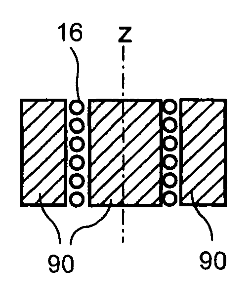
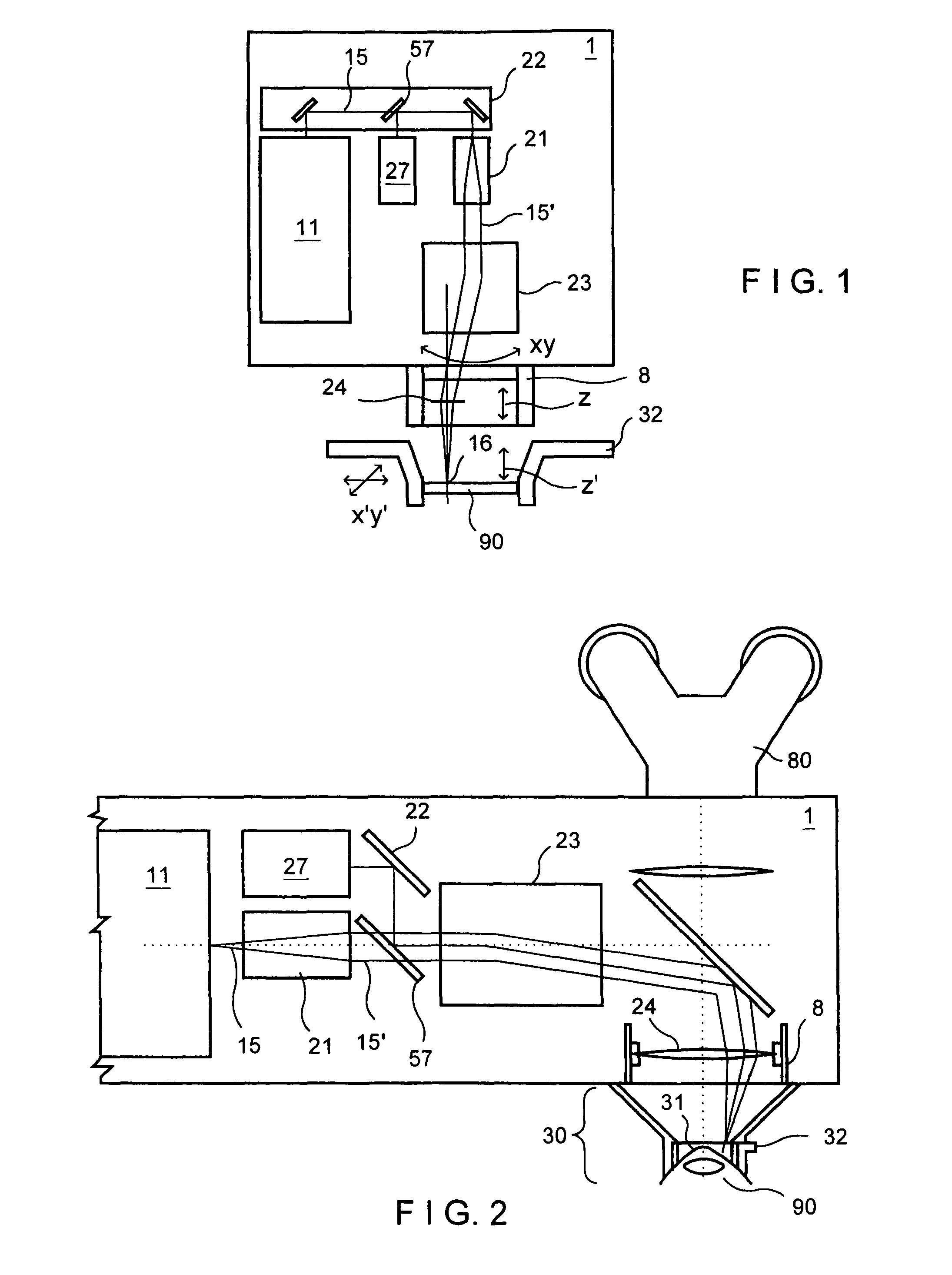
[0058]FIG. 1 shows a schematic view of the individual components of an embodiment example of a laser system according to the invention. The working device 1 comprises an fs laser beam source as radiation source 11. The laser beam 15 is coupled out to beam expansion optics 21 by mirrors and a beam splitter 57. The expanded laser beam 15′ is then guided by a beam deflection device such as a scanner in XY-direction to a beam focusing device 24. The latter is displaceable in the Z-axis and accordingly allows the displacement of the focus point by displacing the beam focusing device along arrow Z. Alternatively, a focusing optical system with variable focal length can be used in order to displace the focus position in Z-direction in a controlled manner. In this way, the focused laser spot 16 is directed onto the material 90 to be worked, which material 90 is held in its position by means of a fixating device 32. In the present instance, the material 90 is a contact lens to be worked. The...


PUM


Abstract

A method for precise working of material, particularly organic tissue, comprises the step of providing laser pulses with a pulse length between 50 fs and 1 ps and with a pulse frequency from 50 kHz to 1 MHz and with a wavelength between 600 and 2000 nm for acting on the material to be worked. Apparatus, in accordance with the invention, for precise working of material, particularly organic tissue comprising a pulsed laser, wherein the laser has a pulse length between 50 fs and 1 ps and with a pulse frequency of from 50 kHz to 1 MHz is also described.

Description

CROSS-REFERENCE TO RELATED APPLICATION[0001]This application is a Continuation Application of application Ser. No. 10 / 625,157, filed Jul. 23, 2003 now U.S. Pat. No. 7,351,241, which claims the priority of U.S. Provisional Application No. 60 / 475,583, filed Jun. 2, 2003, the complete disclosure of which is hereby incorporated by reference.BACKGROUND OF THE INVENTION[0002]a) Field of the Invention[0003]The invention is directed to a femtosecond laser system for precise working of material and tissue, particularly a laser device for the precise, micrometer-exact working of organic material, preferably an eye.[0004]b) Description of the Related Art[0005]In a valuable contribution to the art, German Patent DE 197 46 483 by the present Applicant describes how macroscopic amounts of material are ablated, vaporized or melted (CO2 laser, Nd:YAG, excimer . . . ) with micrometric precision when working over large surface areas of materials by means of lasers with large spot diameters.[0006]In a...

Claims


Application Information

Patent Timeline
Patent Type & Authority Patents(United States)
IPC IPC(8): A61B19/00A61F9/01B23K26/03B23K26/064
CPCA61F9/00827A61F9/00836B23K26/0635A61F2009/00865A61F2009/0087A61F2009/00872A61F2009/00874A61F2009/00868B23K26/0624
Inventor BENDETT, MARKBISCHOFF, MARKGERLACH, MARIOMUEHLHOFF, DIRK
Owner CARL ZEISS MEDITEC AG
Why Eureka
Try Eureka