Eureka AIR delivers breakthrough ideas for toughest innovation challenges, trusted by R&D personnel around the world.

Method of operating ripple counter, image sensor having ripple counter, method of operating image sensor, and analog-to-digital converter of image sensor

a ripple counter and image sensor technology, applied in the field of image sensing technology, can solve the problems of power consumption and output values of the up/down ripple counters, and achieve the effect of reducing the chip size of the cmos image sensor and reducing the chip siz

Active Publication Date: 2012-05-08
SAMSUNG ELECTRONICS CO LTD
View PDF13 Cites 10 Cited by
  • Summary
  • Abstract
  • Description
  • Claims
  • Application Information

AI Technical Summary

Benefits of technology

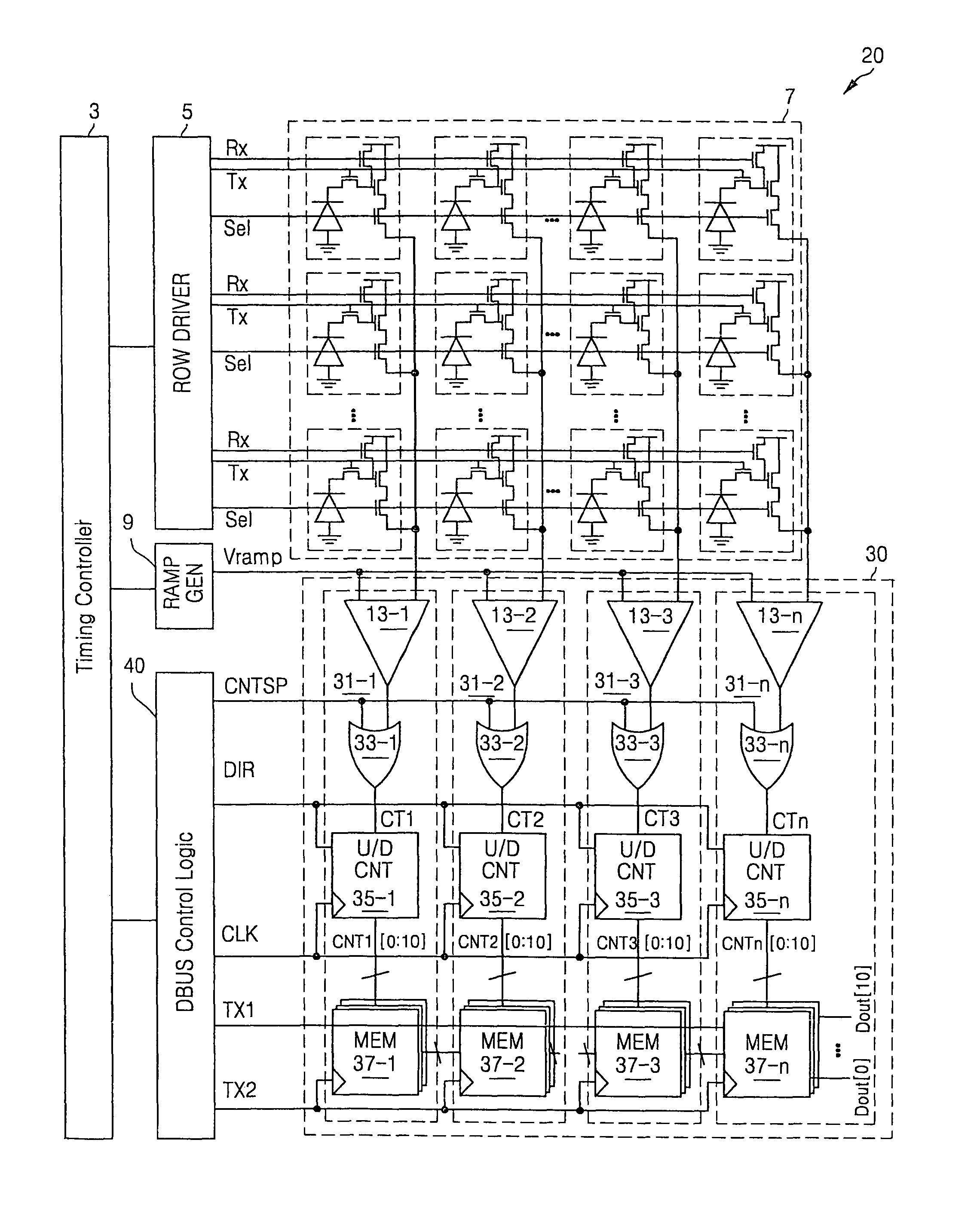
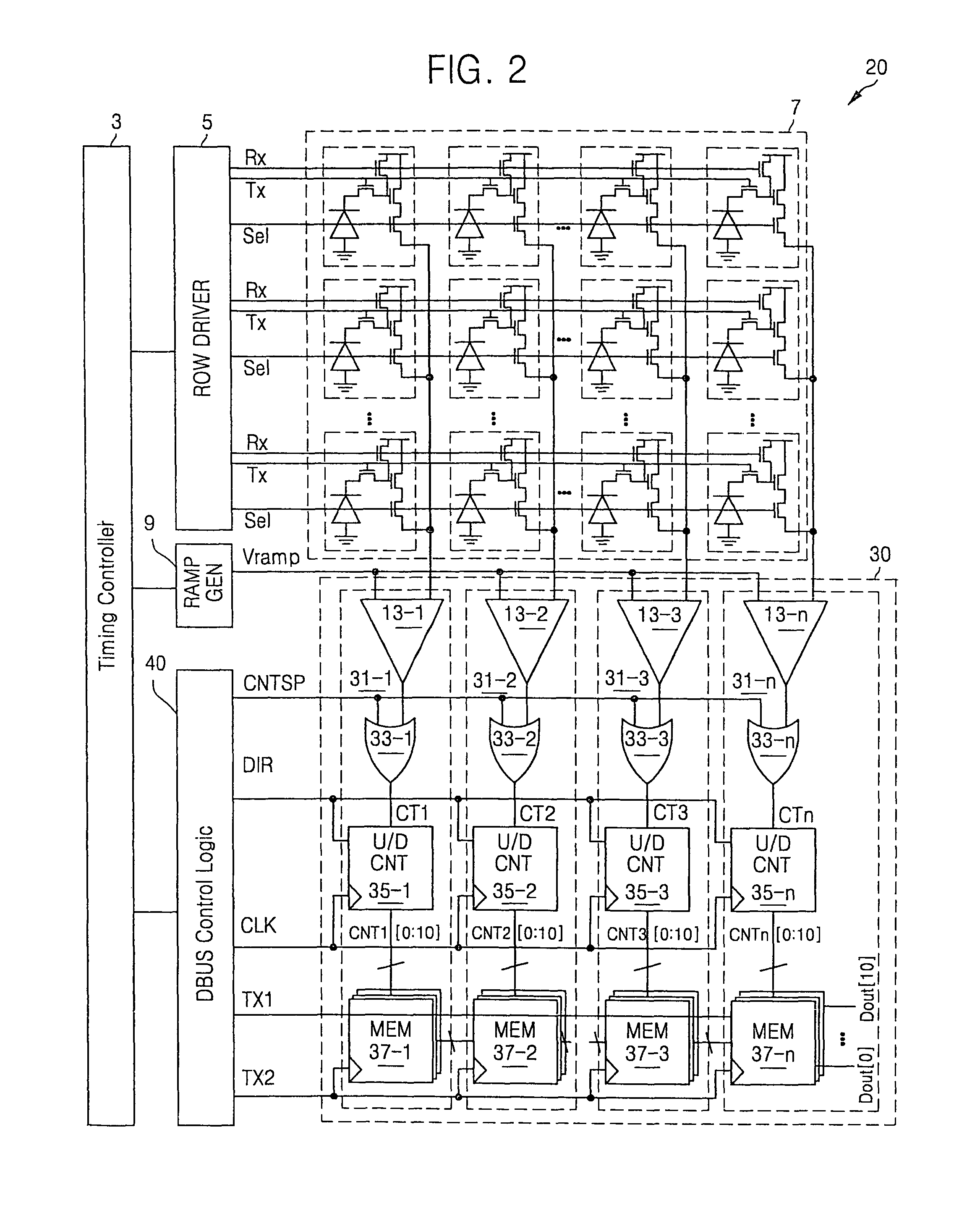
The patent text describes a method to reduce the size of a CMOS image sensor by reducing the size of the ADC (analog-to-digital converter) of the sensor and by optimizing the layout area of the up / down ripple counters and memory devices. The method also increases the data transmission speed of the memory devices. Additionally, the patent describes an image sensor with a controller that generates two control signals, and logic gate circuits and comparison circuits to generate the operation control signals. The image sensor may also include a reference signal generator and multiple memory chains to shift and compare the count values output from the up / down ripple counters. The technical effects of the patent text include reducing the size of the image sensor and increasing its data transmission speed.

Problems solved by technology

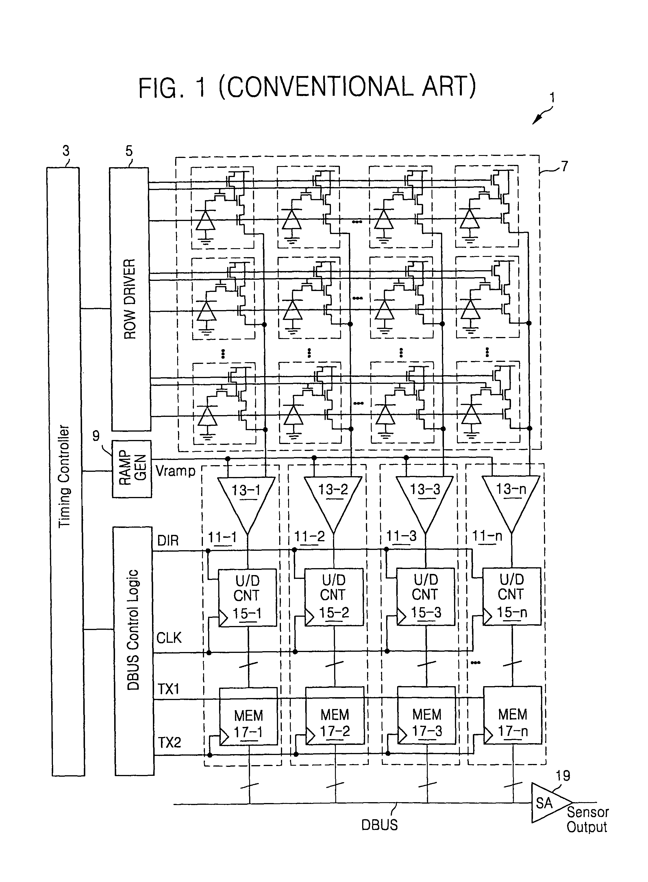
However, since the single ADC is generally operated at high speed, power consumption is generally high.
. . , 15-n, a problem is that output values (e.g., count values) of the up / down ripple counters 15-1, 15-2, 15-3, .

Method used


Image

  • Method of operating ripple counter, image sensor having ripple counter, method of operating image sensor, and analog-to-digital converter of image sensor
  • Method of operating ripple counter, image sensor having ripple counter, method of operating image sensor, and analog-to-digital converter of image sensor
  • Method of operating ripple counter, image sensor having ripple counter, method of operating image sensor, and analog-to-digital converter of image sensor

Examples


Embodiment Construction

[0046]Example embodiments will now be described more fully hereinafter with reference to the accompanying drawings. Embodiments may, however, be in many different forms and should not be construed as being limited to the example embodiments set forth herein. Rather, example embodiments are provided so that this disclosure will be thorough and complete, and will fully convey the scope of this disclosure to those skilled in the art.

[0047]It will be understood that when a component is referred to as being “on,”“connected to” or “coupled to” another component, it can be directly on, connected to or coupled to the other component or intervening components may be present. In contrast, when a component is referred to as being “directly on,”“directly connected to” or “directly coupled to” another component, there are no intervening components present. As used herein, the term “and / or” includes any and all combinations of one or more of the associated listed items.

[0048]It will be understood...


PUM


Abstract

An example embodiment of an image sensor may include a controller and a plurality of up / down ripple counters. The controller may generate a first control signal and a second control signal. Each of the up / down ripple counters may perform a stop operation or a count operation in response to a corresponding one of a plurality of operation control signals generated based on at least in part on the first control signal. The count operation may be an up-count operation or a down-count operation based on the second control signal. The image sensor may also include a plurality of memory chains. Each of the memory chains may receive a count value output from the up / down counters and may shift the received count value in response to a third control signal and a fourth control signal output from the controller.

Description

PRIORITY STATEMENT[0001]This application claims the benefit of Korean Patent Application No. 10-2008-0086980, filed on Aug. 29, 2007, in the Korean Intellectual Property Office, the disclosure of which is incorporated herein in its entirety by reference.BACKGROUND[0002]1. Field of the Invention[0003]Example embodiments relate to an image sensing technology, and more particularly, to a CMOS image sensor having an up / down ripple counter which may prevent the change of data during a count operation. Example embodiments also relate to a method of operating a CMOS image sensor. Also, example embodiments relate to a CMOS image sensor which may allow a reduction in size of an analog-to-digital conversion circuit included in a CMOS image sensor and increase operation speed of the CMOS image sensor.[0004]2. Description of Related Art[0005]Image sensors of semiconductor devices generally convert an optical image to an electric signal. A charge coupled device (CCD) using coupling of charges an...

Claims


Application Information

Patent Timeline
Patent Type & Authority Patents(United States)
IPC IPC(8): H04N3/14H04N5/335H04N23/40H04N25/00
CPCH03K23/62H04N5/37455H04N5/335H04N25/00H04N25/78H04N25/76H04N25/772
Inventor KOH, KYOUNG MIN
Owner SAMSUNG ELECTRONICS CO LTD
Why Eureka
Eureka Blog
Learn More