Seat cushion

a seat cushion and foam technology, applied in the field of seat cushions, can solve the problems of reducing the effectiveness of foam, unable to know or predict accurately, and unable to adapt to environmental conditions, so as to optimize the amount of energy that is absorbed by the seat cushion, reduce the amount of energy, and reduce the effect of foam

Inactive Publication Date: 2012-05-22
US SECREATRY OF THE AIR FORCE THE
View PDF8 Cites 29 Cited by
  • Summary
  • Abstract
  • Description
  • Claims
  • Application Information

AI Technical Summary

Benefits of technology

[0009]A method of absorbing energy in a seat cushion comprises the steps of: supplying a pressurized fluid to each of a plurality of chambers of a seat cushion, wherein the plurality of chambers are in fluid communication with one another; sensing an event; and releasing the pressurized fluid from each of the plurality of chambers of the seat cushion in a controlled manner in response to the sensed event to absorb the optimal amount of energy, thereby reducing the amount of energy that is received by an occupant of the seat cushion.
[0010]A semi-active seat cushion system comprises: a pressurized fluid source; a plurality of chambers for containing a pressurized fluid, wherein each chamber is connected to at least one other chamber by an orifice that provides a fluid connection; a supply conduit for supplying a pressurized fluid to each of the plurality of chambers; a relief valve that permits rapid and controlled deflation of the plurality of chambers; and a controller connected to the relief valve to open the relief valve and control the rate of release of pressurized fluid from the plurality of chambers to optimize the amount of energy that is absorbed by the seat cushion.

Problems solved by technology

While these foams can reduce the probability of injury by slightly lowering the spinal loads that an occupant is exposed to, they have several limitations.
First, they are very sensitive to environmental conditions such as temperature, humidity, and age.
Each of these conditions reduces the effectiveness of the foams.
As such, their performance can never be known or predicted accurately.
In addition, their passive nature prevents them from adjusting to the contours of each individual or adjusting to a particular impact event.
With the increased tempo of military operations, including combat missions that can extend to 40 hours or more, such limitations can reduce air crew comfort and effectiveness.
Moreover, current ejection seats create discomfort, soreness, and numbness.
They also increase overall operator fatigue, particularly during extended missions.
These conditions can adversely affect operator effectiveness.
Another limitation of passive cushions is that they only can absorb a certain amount of energy in a particular way and therefore cannot be designed to provide optimal support and energy absorption for different conditions such as different sized occupants and different impact levels.
Conversely, if a smaller person uses the system, they may not sufficiently load the system during impact to absorb the energy.
These are inherent limitations found in current designs that use passive cushions and foams.

Method used


Image

  • Seat cushion
  • Seat cushion
  • Seat cushion

Examples


Embodiment Construction

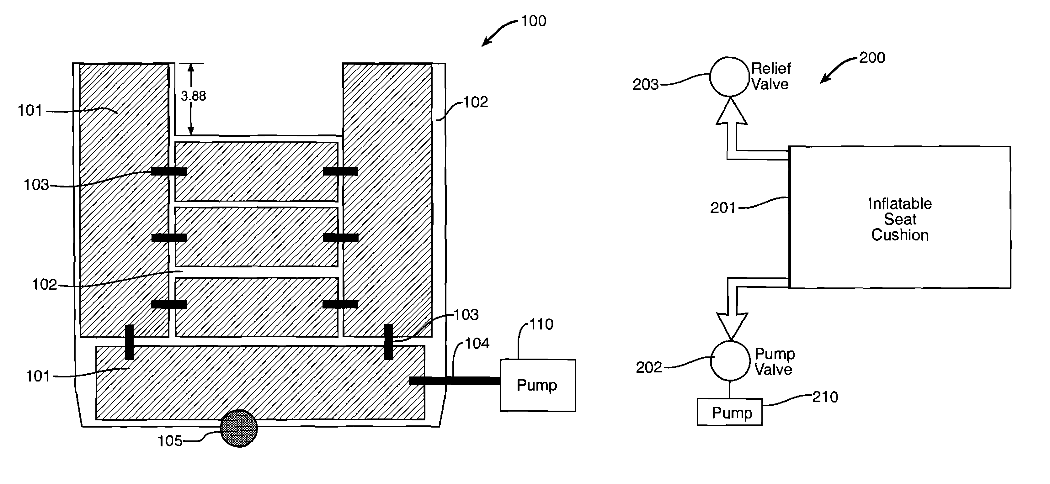
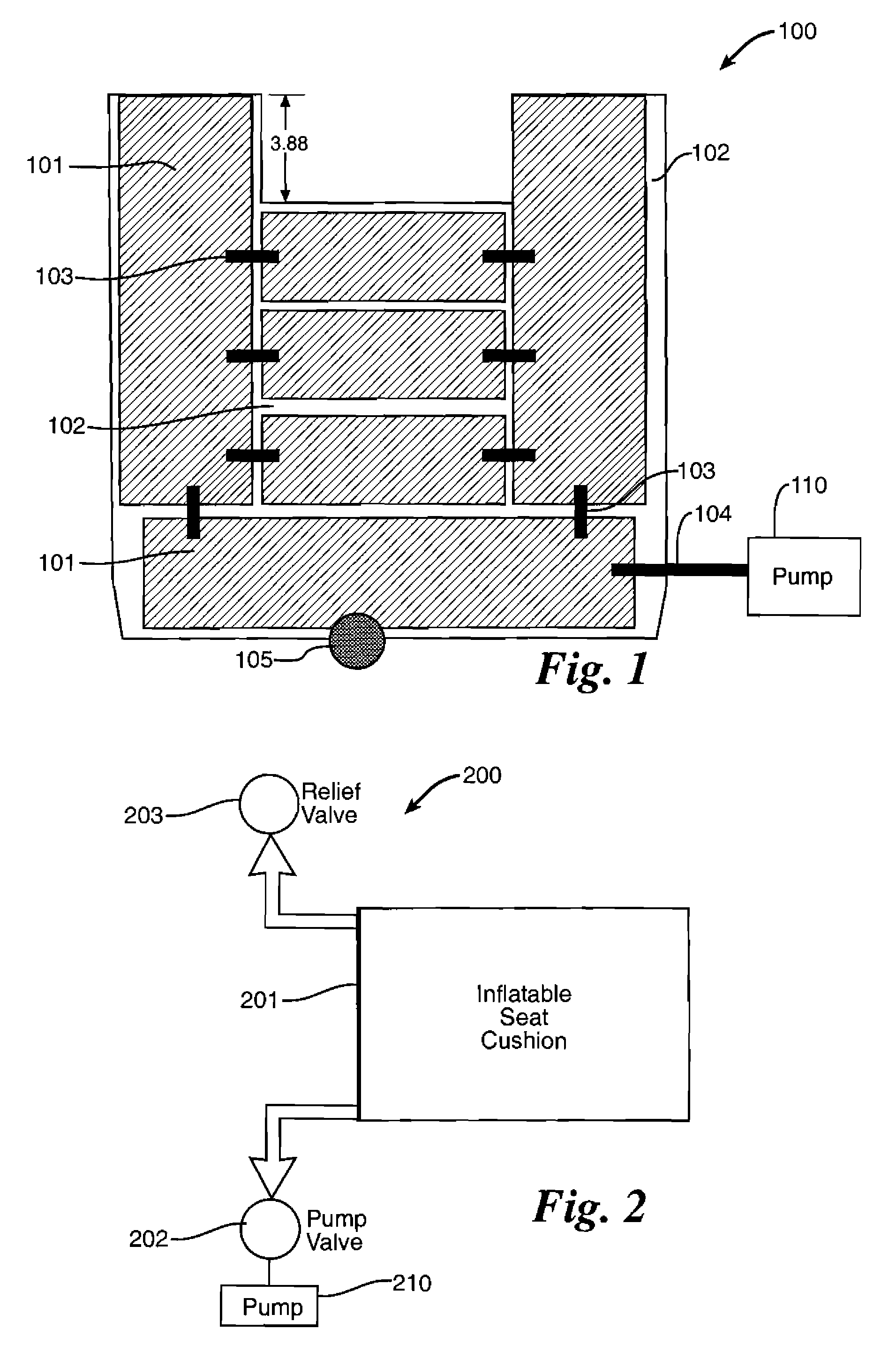
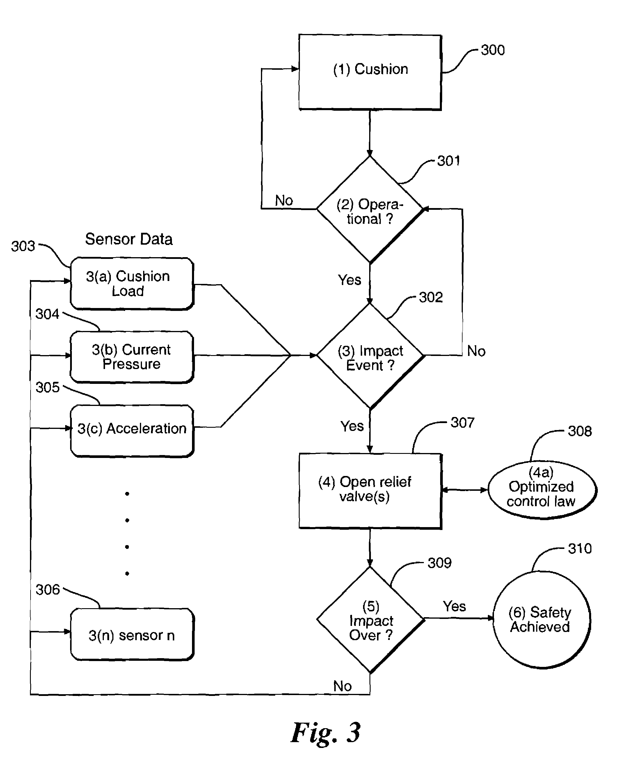
[0014]The disclosed seat cushion uses a semi-active technology. Modeling work has demonstrated the utility of algorithms that can be used to optimize the mechanical properties of seat cushions during a high energy event such as an ejection or an impact by controlling the release of pressurized fluid in the seat cushions.

[0015]In one embodiment, a seat cushion 100 includes a plurality of chambers 101. Each chamber 101 may be the same size and configuration or the chambers 101 may be different sizes and configurations, as shown in FIG. 1. Each chamber 101 is wrapped inside a layer of comfort foam 102. The foam layer 102 can smooth the surface of the seat cushion 100 between the air chambers 101 to eliminate gaps that may be created by different size chambers 101. The foam layer 102 also provides a backup source of cushioning should a leak develop in one of the chambers 101. A sheepskin cover or similar material (not shown) is placed on top of the chambers 101 and the foam layer 102. I...


PUM


Abstract

A semi-active seat cushion is disclosed that comprises a plurality of chambers for containing a pressurized fluid, wherein each chamber is connected to at least one other chamber by an orifice that provides a fluid connection; a supply conduit for supplying a pressurized fluid to each of the plurality of chambers; and at least one relief valve that permits rapid and controlled deflation of the plurality of chambers.

Description

RIGHTS OF THE GOVERNMENT[0001]The inventions described herein may be manufactured and used by or for the Government of the United States for all governmental purposes without the payment of any royalty.BACKGROUND OF THE INVENTION[0002]Seat cushions currently used in automotive, aircraft, and military vehicles are generally passive in nature. That is, they rely on the use of rate sensitive foams to cushion occupants and absorb energy from impacts, and from the catapult phase of an ejection in the case of aircraft. While these foams can reduce the probability of injury by slightly lowering the spinal loads that an occupant is exposed to, they have several limitations. First, they are very sensitive to environmental conditions such as temperature, humidity, and age. Each of these conditions reduces the effectiveness of the foams. As such, their performance can never be known or predicted accurately. In addition, their passive nature prevents them from adjusting to the contours of each ...

Claims


Application Information

Patent Timeline
Patent Type & Authority Patents(United States)
IPC IPC(8): B64D25/04B60N2/42A47C27/10B64D25/10
CPCB60N2/42709B60N2/42727B60N2/4279B64D11/0647B64D11/0689B64D25/04B64D11/0619B60N2/4415B60N2/914B60N2/42754
Inventor PELLETTIERE, JOSEPH A.
Owner US SECREATRY OF THE AIR FORCE THE
Why Eureka
Try Eureka