Apparatus and method for cooling turbomachine exhaust gas

a technology of exhaust gas and turbomachine, which is applied in the direction of machines/engines, engine starters, turbine/propulsion engine ignition, etc., can solve the problems of increasing complexity and cost of operation of turbomachin

Inactive Publication Date: 2012-05-29
GENERAL ELECTRIC CO
View PDF43 Cites 38 Cited by
  • Summary
  • Abstract
  • Description
  • Claims
  • Application Information

AI Technical Summary

Benefits of technology

[0003]According to one aspect of the invention, a turbomachine includes at least one exhaust pathway along which exhaust is directed and released to an ambient environment and at least one exhaust processor capable of removing substances from the exhaust. One or more ambient air inlets are located at the exhaust pathway upstream of the exhaust processor. The at least one exhaust pathway is configured to reduce a pressure of exhaust therein to draw ambient air into the at least one exhaust pathway via the one or more ambient air inlets. The ambient air reduces a temperature of the exhaust to increase effectiveness of the at least one exhaust processor.
[0004]According to another aspect of the invention, a method for releasing turbomachine exhaust to an ambient environment includes accelerating exhaust along at least one exhaust pathway and lowering a pressure of the exhaust in the at least one exhaust pathway. The method further includes drawing ambient air into the at least one exhaust pathway through one or more ambient air inlets via the lowering of the pressure of the exhaust, thereby reducing a temperature of the exhaust, and dispensing the exhaust to an ambient environment.

Problems solved by technology

These fan systems must be capable of high flow rates and high pressures and increase complexity and cost to operation of the turbomachinery.

Method used


Image

  • Apparatus and method for cooling turbomachine exhaust gas
  • Apparatus and method for cooling turbomachine exhaust gas
  • Apparatus and method for cooling turbomachine exhaust gas

Examples


Embodiment Construction

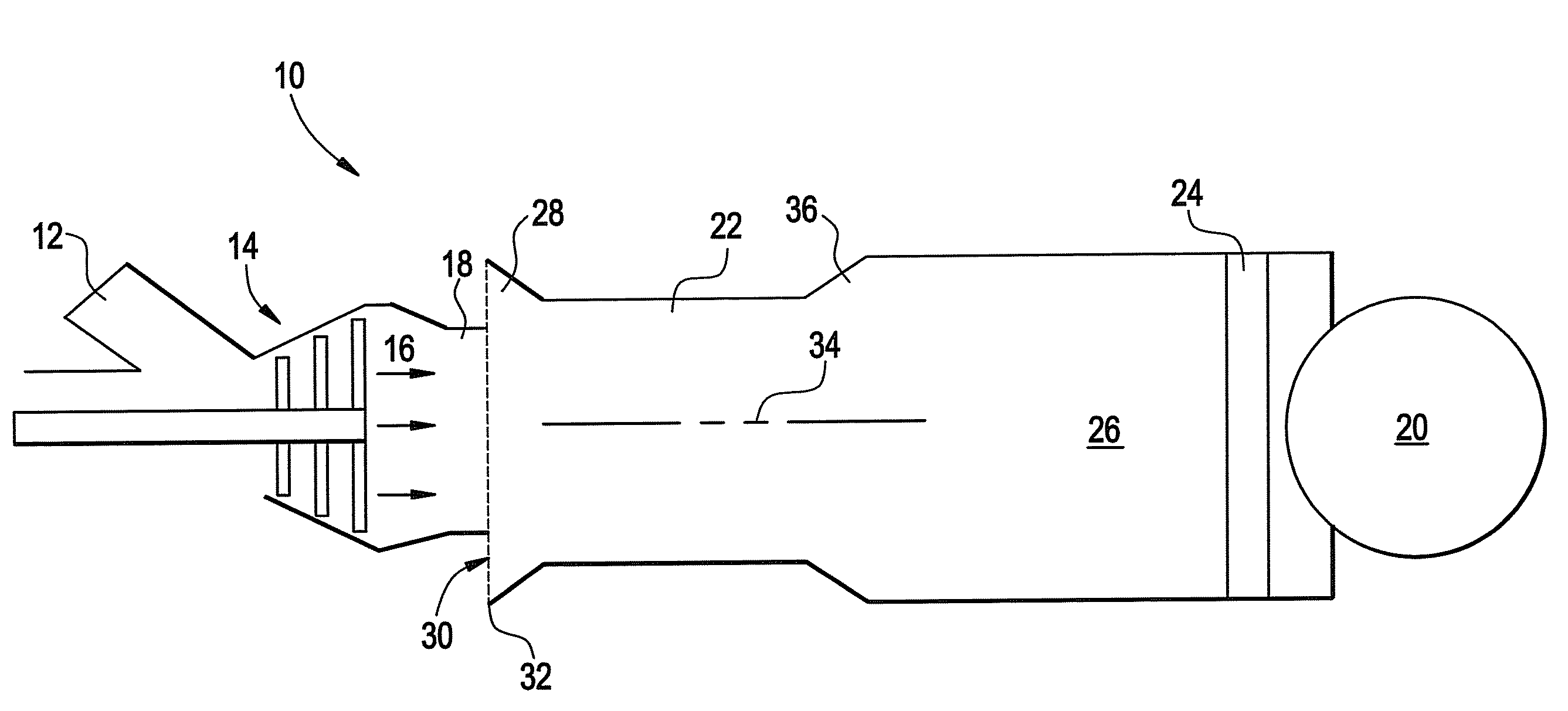
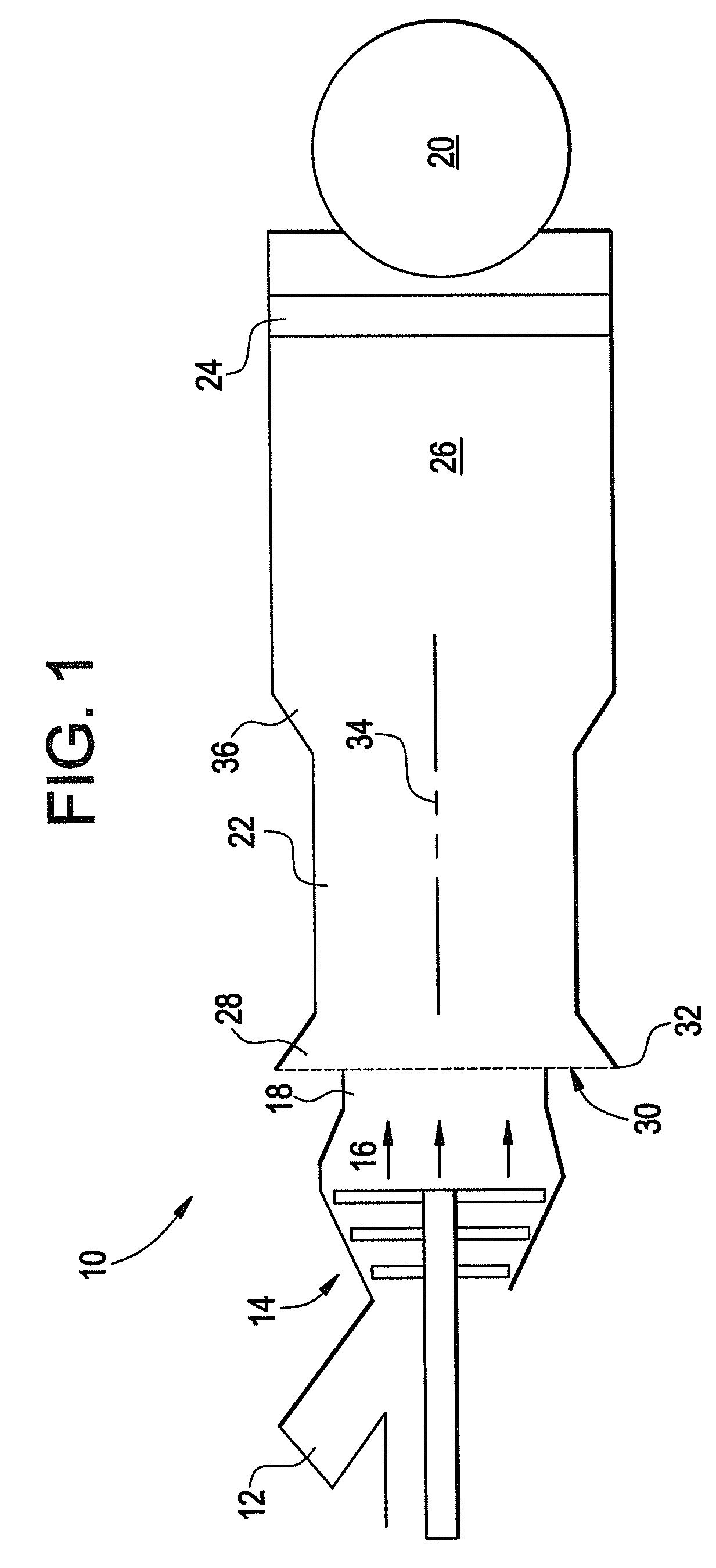
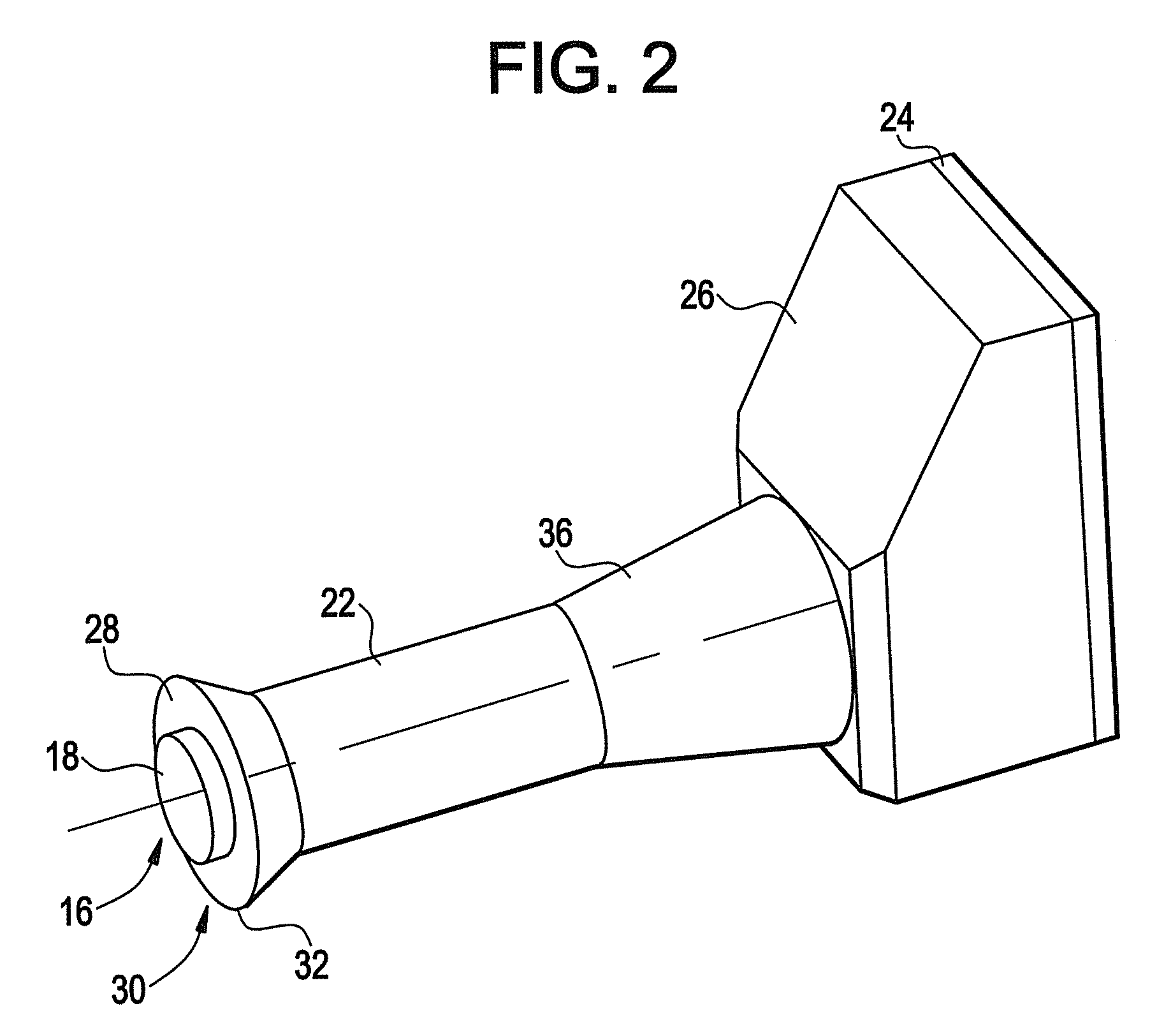
[0011]Shown in FIG. 1 is a schematic illustration of an embodiment of a turbomachine, for example, a gas turbine 10. The gas turbine 10 includes one or more combustors 12 in which fuel and compressed air are mixed and ignited. The hot gas product of the combustion flows to a turbine 14 which extracts work from the hot gas. After flowing through the turbine 14, the hot gas or exhaust 16, flows through an exhaust port 18 toward a stack 20 via a mixing duct 22 for release into atmosphere.

[0012]To reduce an amount of undesired substances, for example, NOx released into the atmosphere from the stack 20, the exhaust 16 is urged through an exhaust processor, in some embodiments a Selective Catalytic Reduction (SCR) system 24 prior to release into the atmosphere. As shown in FIG. 1, the SCR system 24 is, in some embodiments, disposed between the mixing duct 22 and the stack 20 at, for example, a transition duct 26. It is to be appreciated, however, that the SCR system 24 may be disposed in ...


PUM


Abstract

Disclosed is a turbomachine including at least one exhaust pathway along which exhaust is directed and released to ambient and at least one exhaust processor capable of removing regulated substances from the exhaust. One or more ambient air inlets are located at the at least one exhaust pathway upstream of the at least one exhaust processor. The at least one exhaust pathway is configured such that ambient air is capable of being urged into the at least one exhaust pathway through the one or more ambient air inlets by an acceleration of the exhaust along the at least one exhaust pathway. The ambient air urged into the at least one exhaust pathway reduces a temperature of the exhaust to increase effectiveness of the at least one exhaust processor. Further disclosed is a method for releasing turbomachine exhaust to ambient.

Description

BACKGROUND[0001]The subject invention relates to turbomachinery. More particularly the subject invention relates to cooling of exhaust gas of turbomachinery.[0002]Exhaust gas from turbomachinery, for example a gas turbine power generation plant, often must meet stringent regulatory requirements for composition of the exhaust gas released into the atmosphere. One of the components typically found in exhaust gas and subject to regulation is NOx. To remove the NOx from the exhaust stream, technology such as Selective Catalytic Reduction (SCR) is often utilized. In an SCR process, ammonia (NH3) or the like reacts with the NOx and produces nitrogen (N2) and water (H2O). Effectiveness of the SCR process depends on the temperature of the exhaust gas which is processed. Exhaust gas from the turbomachinery is often about 1100 degrees F., and must be cooled prior to SCR to increase the effectiveness of SCR to meet requirements. This cooling is typically achieved by diluting the exhaust gas wi...

Claims


Application Information

Patent Timeline
Patent Type & Authority Patents(United States)
IPC IPC(8): F01N3/10
CPCF01D25/30F02C6/00F01N3/05F05D2270/082F05D2260/601F05D2250/232
Inventor ZHANG, HUABALL, JR., DAVID WESLEYTAYLOR, THOMAS FRANCIS
Owner GENERAL ELECTRIC CO
Why Eureka
Try Eureka