Interbody fusion system with intervertebral implant retention assembly

a fusion system and intervertebral technology, applied in the field of intervertebral implants and intervertebral implant assemblies, can solve the problems of reducing esophageal compression and reducing the profile, and achieve the effect of minimizing irritation of soft tissue, eliminating the exacerbation of instability, and reducing the risk of fractur

Active Publication Date: 2012-05-29
SPARTAN CAGE HLDG
View PDF102 Cites 92 Cited by
  • Summary
  • Abstract
  • Description
  • Claims
  • Application Information

AI Technical Summary

Benefits of technology

[0016]The present invention is directed towards an integratable biomechanical implant construct comprising plural components inclusive of 1) a biomechanical spacer implant for insertion within an intervertebral space, 2) an anterior, posterior or lateral instrumentation component effective for vertebral body fixation and maintenance of the biomechanical spacer implant within the intervertebral space, and 3) a plurality of fastener components effective for securing the biomechanical implant construct to the vertebral bodies. The biomechanical spacer implant and anterior instrumentation component are designed for removable locking engagement, one with the other, for insertion by the surgeon as a unitary construct. It is contemplated that the biomechanical implant construct may be of either a unitary or a modular construction. When a unitary construction is provided, a single molded construction, e.g. of PEEK, titanium, or the like, can form the entire construct. In the case where the unitary construct is formed from a polymeric material, the through holes formed within the anterior instrumentation component may be reinforced for retention of the screw retainer components by incorporation of a metallic insert to make possible the novel anterior instrumentation / fastener component locking feature specific to the present invention.
[0017]A unique feature of the construct resides within the anterior instrumentation construction, whereby a single opening formed within the anterior instrumentation permits two bone screws, or the like fastener elements, to be positioned within both the superior and inferior vertebral bodies surrounding the spacer implant or, for example in the case of a corpectomy or diskectomy with cage insertion, wherein two screws can be fixed within a single vertebral body through a single through hole, and wherein the bone screws are constructed and arranged to cooperate with the anterior instrumentation so as to provide locking engagement, one to the other, with the anterior instrumentation, upon final fixation thereof. The use of a single screw hole allows the use of a relatively smaller faceplate than is possible with prior art designs, thus providing a more compact device which decreases the profile of the implant and concomitantly results in a decrease in esophageal compression.
[0019]As an additional safety feature to guard against screw separation in the event of accidental backing out or breakage of the screws, a unique screw retainer component is further provided. The screw retainer component comprises an “open eight” retention clip within an area of the anterior instrumentation designed to receive it. In the horizontal spaced orientation the screw retainer component is illustrated as being in the form of a planar retention clip, while in the vertical spaced orientation, the clip is bent to conform to the internal shape of the anterior instrumentation access hole. In both cases, the screw retainer component is designed to deflect during insertion of each screw, and then return to its original position to prevent a loosened or broken screw from falling out of the anterior instrumentation.
[0020]The implant of the present invention preferably may be inserted using a one-step implantation process, as compared to a two-step process. Furthermore, the aspect is minimized due to the novel construction of the retention plate portion, thereby permitting the inferior and superior fixation to be essentially coplanar, thus eliminating the exacerbation of instability that may be caused by off-center loading resulting from the placement of multiple fasteners about areas of flexion or extension. The use of minimal aspect fixation should further minimize irritation of soft tissue, while providing improved segmental stability in flexion, extension and rotation.
[0021]Accordingly, it is an objective of the instant invention to provide a biomechanical implant and anterior instrumentation construct comprised of an intervertebral implant and a retention member which are constructed and arranged to form a permanent, rigid connection with bone fixation elements, so that, even if the bone structure is weakened, there is no loosening between the anterior instrumentation and the bone fixation elements. Moreover, the construct with biomechanical implant (stabilizer) enables superior and inferior vertebral fixation by multiple bone fixation elements via a single through hole, such that, upon fixation to the bony elements, said multiple fixation elements are in frictional engagement with each other and with the implant retention member, whereby all bone fixation elements are secured simultaneously.
[0022]It is an additional objective of the instant invention to provide a screw retainer component to guard against escape of a dislodged screw from the device.

Problems solved by technology

The use of a single screw hole allows the use of a relatively smaller faceplate than is possible with prior art designs, thus providing a more compact device which decreases the profile of the implant and concomitantly results in a decrease in esophageal compression.

Method used


Image

  • Interbody fusion system with intervertebral implant retention assembly
  • Interbody fusion system with intervertebral implant retention assembly
  • Interbody fusion system with intervertebral implant retention assembly

Examples


Embodiment Construction

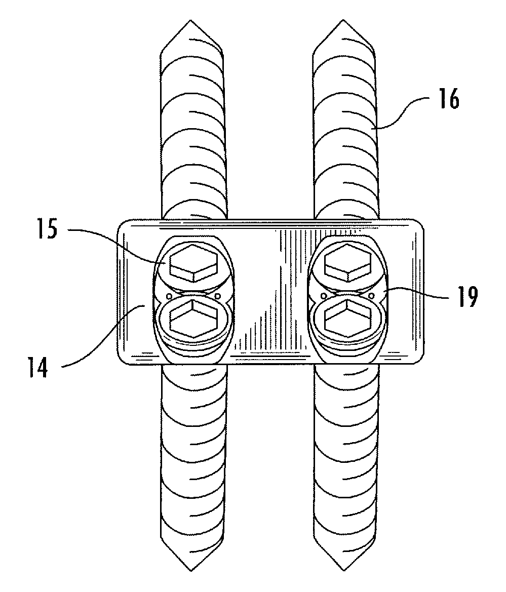
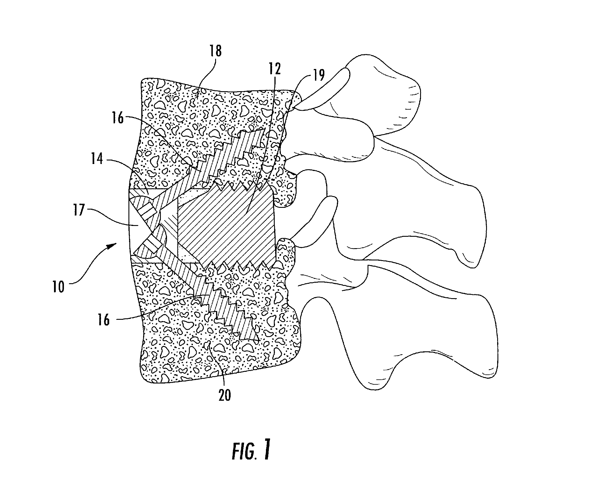
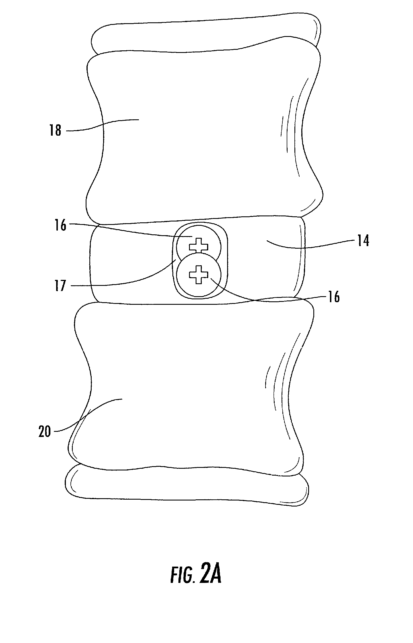
[0052]Now referring to FIG. 1, the intervertebral implant assembly, generally referred to by numeral 10, includes an implant member 12, and a retention member 14, illustrated as, albeit not limited to, a bone plate. Both plate 14 and implant 12 may be formed of PEEK (poly(ether ether ketone)), titanium, titanium alloy, stainless steel, allograft bone or any other suitable, biocompatible material. It is contemplated that implant 12 may be formed of bone, or an artificial material other than bone which may be harder and / or stronger than bone, such as plastic or ceramic materials. It is further contemplated that the implant material will have the same, more or less elasticity than bone. The implant 12 may include, or be treated with, a bone growth promoting material such as, but not limited to, bone morphogenic protein, hydroxyapatite, and genes coding for the production of bone. Implant 12 may be a source for osteogenesis, be at least in part bioabsorbable, and be treated with, or app...


PUM

PropertyMeasurementUnit
angleaaaaaaaaaa
angleaaaaaaaaaa
thicknessaaaaaaaaaa

Abstract

The present disclosure is directed towards a biomechanical implant and anterior, lateral or posterior instrumentation construct. The construct may be of unitary or modular construction, whereby a single molded construction can form the entire assembly, in which case the through holes may be adapted to receive a metallic insert for screw fixation; or alternatively be of a modular construction wherein the anterior / lateral instrumentation and intervertebral spacer are designed for removable locking engagement, one with the other, for insertion by the surgeon as a unitary construct. A unique feature of the construct resides within the instrumentation construction, whereby a single opening formed therein permits two bone screws, or the like fastener device, to be positioned within both the superior and inferior vertebral bodies surrounding the spacer implant, or, for example in the case of a corpectomy or diskectomy with cage insertion, wherein two screws can be fixed within a single vertebral body through a single through hole, and wherein the bone screws are constructed and arranged to cooperate with the retention plate so as to provide locking engagement, one to the other, with the retention plate, upon final fixation thereof. Screw retention elements of alternative shape, based upon the choice of vertical or horizontal orientation, based upon an opened figure eight design, are provided for insertion in a groove formed in the borehole of the instrumentation plate which allows insertion of each fixation element but will prevent a loosened fixation element from falling out of the plate.

Description

CROSS-REFERENCE TO RELATED APPLICATIONS[0001]This application claims benefit of the filing date of U.S. Provisional Patent Application No. 61 / 154,038, filed on Feb. 20, 2009, and U.S. Provisional Patent Application No. 61 / 239,230, filed on Sep. 2, 2009, the contents of each of which is herein incorporated by reference in their entirety.FIELD OF THE INVENTION[0002]The present invention relates generally to an interbody fusion system having an intervertebral retention assembly, and more particularly to intervertebral implants, and intervertebral implant assemblies incorporating a biomechanical implant construct inclusive of stabilizing instrumentation (an anterior, posterior or lateral stabilizer), constructed and arranged to provide superior and inferior vertebral fixation by multiple fixation elements via a single through hole, which through hole can accommodate a fixation element retainer component (hereinafter referred to as a screw retainer component, e.g. a third piece of instru...

Claims


Application Information

Patent Timeline
Patent Type & Authority Patents(United States)
IPC IPC(8): A61F2/44
CPCA61F2/4455A61B17/86A61F2310/00029A61F2002/30062A61F2002/30354A61F2002/30387A61F2002/30481A61F2002/30514A61F2002/30578A61F2002/30604A61F2002/30787A61F2002/30794A61F2002/30843A61F2002/30884A61F2002/30892A61F2002/30904A61F2210/0004A61F2220/0025A61F2220/0033A61F2310/00017A61F2310/00023A61F2/30744A61F2002/3079
Inventor THEOFILOS, CHARLES S.
Owner SPARTAN CAGE HLDG
Why Eureka
Try Eureka