
Method and apparatus for producing a three-dimensionally shaped object, and three dimensionally shaped object

a three-dimensional object and object technology, applied in the direction of additive manufacturing processes, manufacturing tools, electric/magnetic/electromagnetic heating, etc., can solve the problems of reducing the transmittance of light beams, and inability to produce intended shaped objects. , to achieve the effect of avoiding failure to stabilize sintering or inability to increase the density of a sintered portion

Inactive Publication Date: 2012-05-29
PANASONIC CORP
View PDF6 Cites 43 Cited by
  • Summary
  • Abstract
  • Description
  • Claims
  • Application Information

AI Technical Summary

Benefits of technology

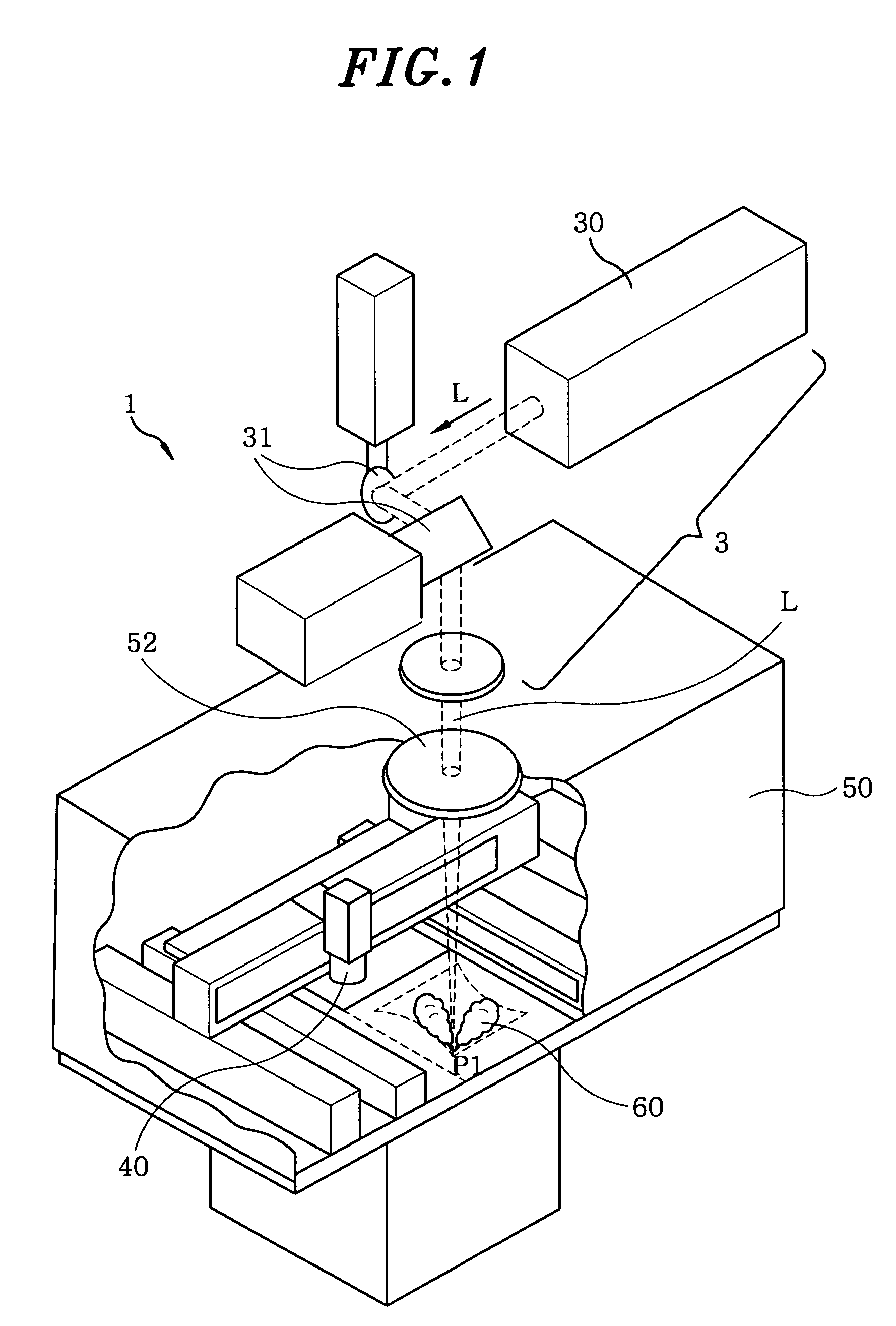
[0006]In view of the above, the present invention provides a method for producing a three-dimensionally shaped object, which is capable of suppressing the influence of fumes as far as possible.
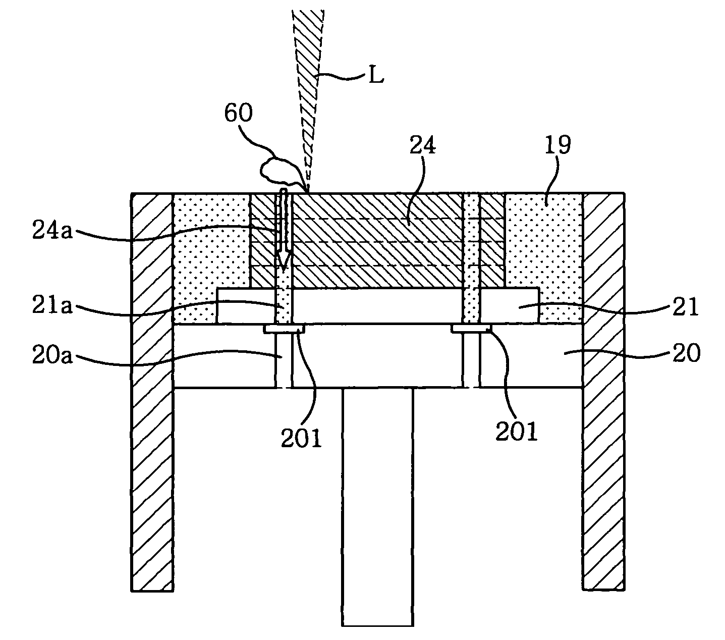
[0030]With the present invention, the fumes generated by the irradiation of light beam are effectively removed from the chamber. This makes it possible to prevent the light transmissive window of the chamber from becoming opaque. In other words, it is possible to prevent reduction in the transmittance of the light beam irradiated into the chamber, which makes it possible to obtain a desired solidified layer. More specifically, it is possible to avoid the failure to stabilize sintering or the inability to increase the density of a sintered portion, which would otherwise occur when the powder layer is a metal powder layer and the solidified layer is a sintered layer. This makes it possible to keep substantially uniform the strength of the three-dimensionally shaped object.
[0031]With the present invention, the fumes are sucked and removed downwards from the vicinity of a fume generation point. This restrains the fumes from moving upwards. Therefore, there is no possibility that the light beam path is interrupted by the fumes and that the irradiation amount of the light beam irradiated on the powder layer is reduced. In other words, it is possible to prevent reduction in the light beam energy which would otherwise be caused by the upward movement of fumes. In addition, the fumes are removed from the chamber as soon as they are generated. Thus the dirt originating from the fumes is prevented from adhering to the inner wall portion of the chamber. This provides an advantageous effect in that the chamber can enjoy improved maintainability.

Problems solved by technology

The fumes move upwards to adhere to the light transmissive window or burn, which may reduce the light beam transmittance of the light transmissive window.
Reduction in the light beam transmittance makes it impossible to obtain a desired solidified layer and to produce an intended shaped object.
In case where a metal powder layer is used as the powder layer, the reduced light beam transmittance results in failure to stabilize sintering or inability to increase sintering density.
This poses a problem in that the three-dimensionally shaped object shows a decrease in strength.
In addition, the fumes may directly affect the light beam irradiated into the chamber.
In other words, there is a fear that, due to the interruption of the light beam path by the upwardly moving fumes, the energy quantity of light beam delivered to the powder layer may be substantially smaller than a specified value.

Method used


Image

  • Method and apparatus for producing a three-dimensionally shaped object, and three dimensionally shaped object
  • Method and apparatus for producing a three-dimensionally shaped object, and three dimensionally shaped object
  • Method and apparatus for producing a three-dimensionally shaped object, and three dimensionally shaped object

Examples


Embodiment Construction

[0045]Hereinafter, preferred embodiments of the present invention will be described in detail with reference to the accompanying drawings.

[0046](Selective Laser Sintering or Melting)

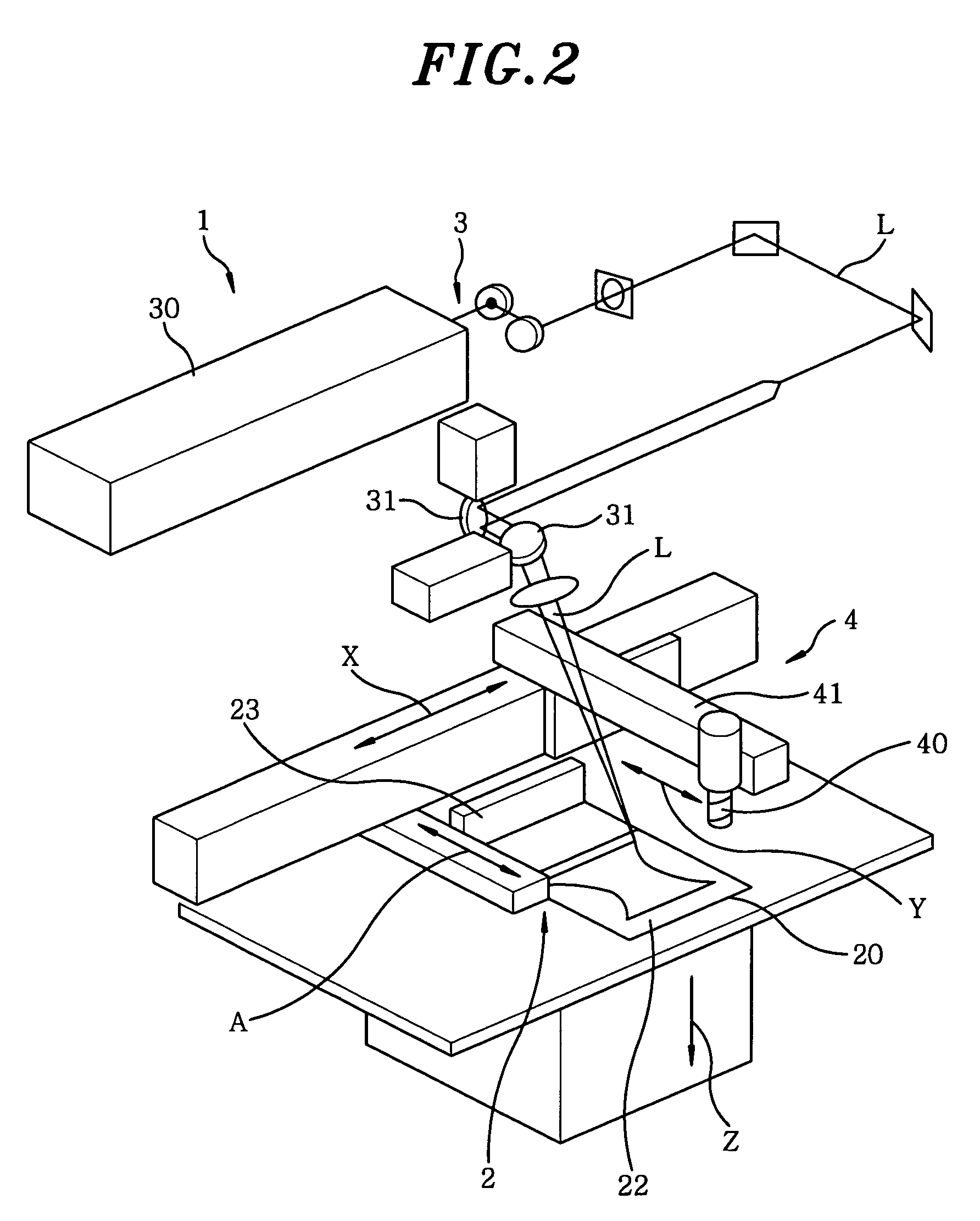
[0047]Description will be first made on Selective Laser Sintering or Melting as a premise of the present production method. FIG. 2 shows the configuration of a combined optical shaping machine 1 for use in performing Selective Laser Sintering or Melting. The combined optical shaping machine 1 mainly includes a powder layer forming unit 2 for forming a powder layer by spreading a powder such as a metal powder or a resin powder in a specified thickness, a shaping table 20 (see FIGS. 4A and 4B) vertically movable by the operation of a cylinder within a shaping tank 29 whose outer periphery is surrounded by a wall 27, a light beam irradiation unit 3 for irradiating a light beam L on an arbitrary position, and a cutting unit 4 for cutting the peripheral portion of a shaped object. As shown in FIGS. 4A and 4B,...


PUM

PropertyMeasurementUnit
particle sizeaaaaaaaaaa
diameteraaaaaaaaaa

Abstract

A method for producing a three-dimensionally shaped object, includes the steps of: (i) forming a solidified layer by irradiating a light beam on a specified portion of a powder layer placed on a shaping table to sinter or melt the specified portion; (ii) forming another solidified layer by placing a new powder layer on the solidified layer thus obtained, and irradiating the light beam on a specified portion of the new powder layer to sinter or melt the specified portion of the new powder layer; and (iii) repeating the step (ii) to produce a three-dimensionally shaped object. When performing the steps (i) to (iii) within a chamber, at least a part of an ambient gas in the chamber is exhausted from the chamber through a gas passage of a shaping tank.

Description

FIELD OF THE INVENTION[0001]The present invention relates to a method for producing a three-dimensionally shaped object, an apparatus for producing the same, and a three-dimensionally shaped object. More specifically, the present invention pertains to a method for producing a three-dimensionally shaped object having a plurality of solidified layers laminated one above another by repeating the step of irradiating a light beam on a specified portion of a powder layer to form a solidified layer, an apparatus for producing a three-dimensionally shaped object, and a three-dimensionally shaped object thus produced.BACKGROUND OF THE INVENTION[0002]Conventionally, there is known a method for producing a three-dimensionally shaped object by irradiating a light beam on a powdery material, which method is usually referred to as “Selective Laser Sintering or Melting”. In this method, the three-dimensionally shaped object is produced by repeating (i) a step of irradiating a light beam on a speci...

Claims


Application Information

Patent Timeline
Patent Type & Authority Patents(United States)
IPC IPC(8): B29B17/00B29C35/08B29C41/02
CPCB22F3/003B22F3/1055B29C67/0077B22F2003/1056B29C64/153B33Y40/00B33Y10/00Y02P10/25B22F10/28B22F10/32B22F12/70B22F10/77
Inventor HIGASHI, YOSHIKAZUTAKENAMI, MASATAKAABE, SATOSHIFUWA, ISAOYOSHIDA, NORIO
Owner PANASONIC CORP
Learn More