
Combustion turbine component having bond coating and associated methods

a combustion turbine and component technology, applied in the field of metalurgical field, can solve the problems of undesirable component wear and/or failure, brittleness of the bond coating, etc., and achieve the effects of preventing thermal barrier coating spallation, enhancing oxidation protection, and high temperature operation

Inactive Publication Date: 2012-06-05
SIEMENS ENERGY INC
View PDF18 Cites 26 Cited by
  • Summary
  • Abstract
  • Description
  • Claims
  • Application Information

AI Technical Summary

Benefits of technology

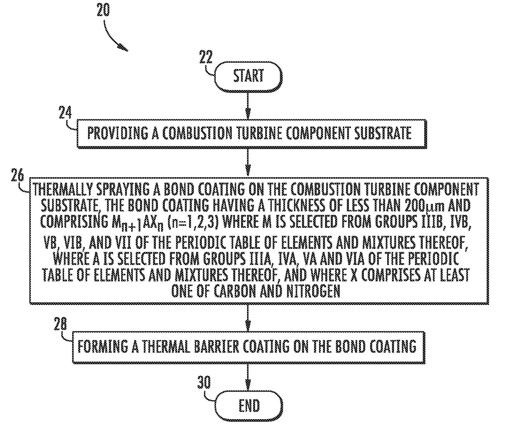
"The present invention provides a combustion turbine component with an enhanced bond coating that protects against oxidation and damage caused by foreign materials. The bond coating is made of Mn+1AXn (n=1,2,3) where M is selected from groups IIIB, IVB, VB, VIB, and VII of the periodic table of elements and mixtures thereof, and A is selected from groups IIIA, IVA, VA, and VIA of the periodic table of elements and mixtures thereof, and X comprises at least one of carbon and nitrogen. A thermal barrier coating may be applied on top of the bond coating. The bond coating has a nanolaminate microstructure and a thickness of less than 200 μm. The method of making the combustion turbine component involves thermally spraying the bond coating onto the substrate using at least one of high velocity oxygen fuel (HVOF) spraying, low velocity oxygen fuel (LVOF) spraying, plasma spraying, and flame spraying."

Problems solved by technology

This bond coating may be effective at maintaining the bond between the thermal barrier coating and the substrate up to about 1200° C. However, at temperatures greater than 1200° C., such a MCrAlY bond coating may become brittle and spallation (delamination and ejection) of the thermal barrier coating from the substrate may occur.
Such spallation may lead to undesirable component wear and / or failure.

Method used


Image

  • Combustion turbine component having bond coating and associated methods
  • Combustion turbine component having bond coating and associated methods
  • Combustion turbine component having bond coating and associated methods

Examples


Embodiment Construction

[0022]The present invention will now be described more fully hereinafter with reference to the accompanying drawings, in which preferred embodiments of the invention are shown. This invention may, however, be embodied in many different forms and should not be construed as limited to the embodiments set forth herein. Rather, these embodiments are provided so that this disclosure will be thorough and complete, and will fully convey the scope of the invention to those skilled in the art. Like numbers refer to like elements throughout.

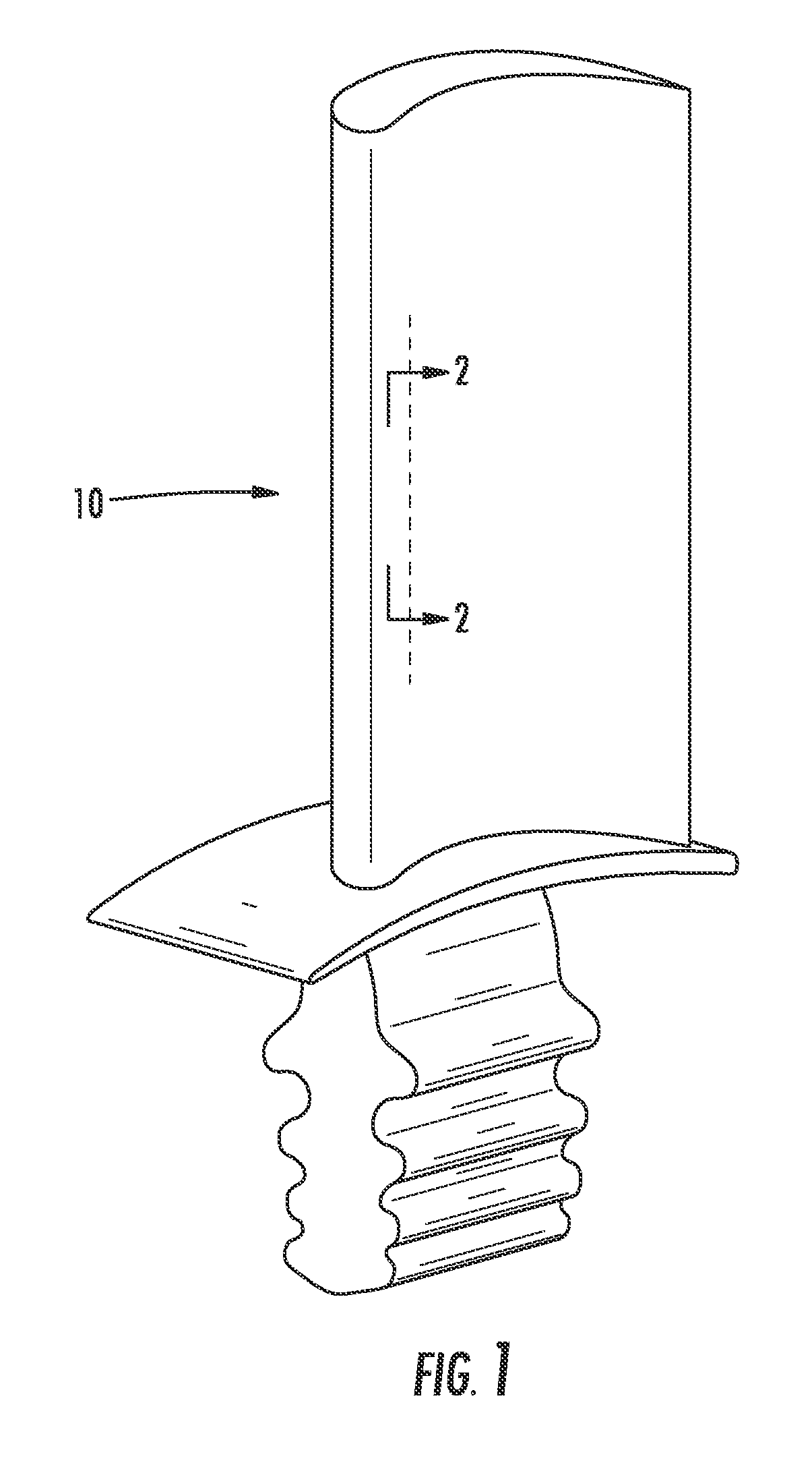
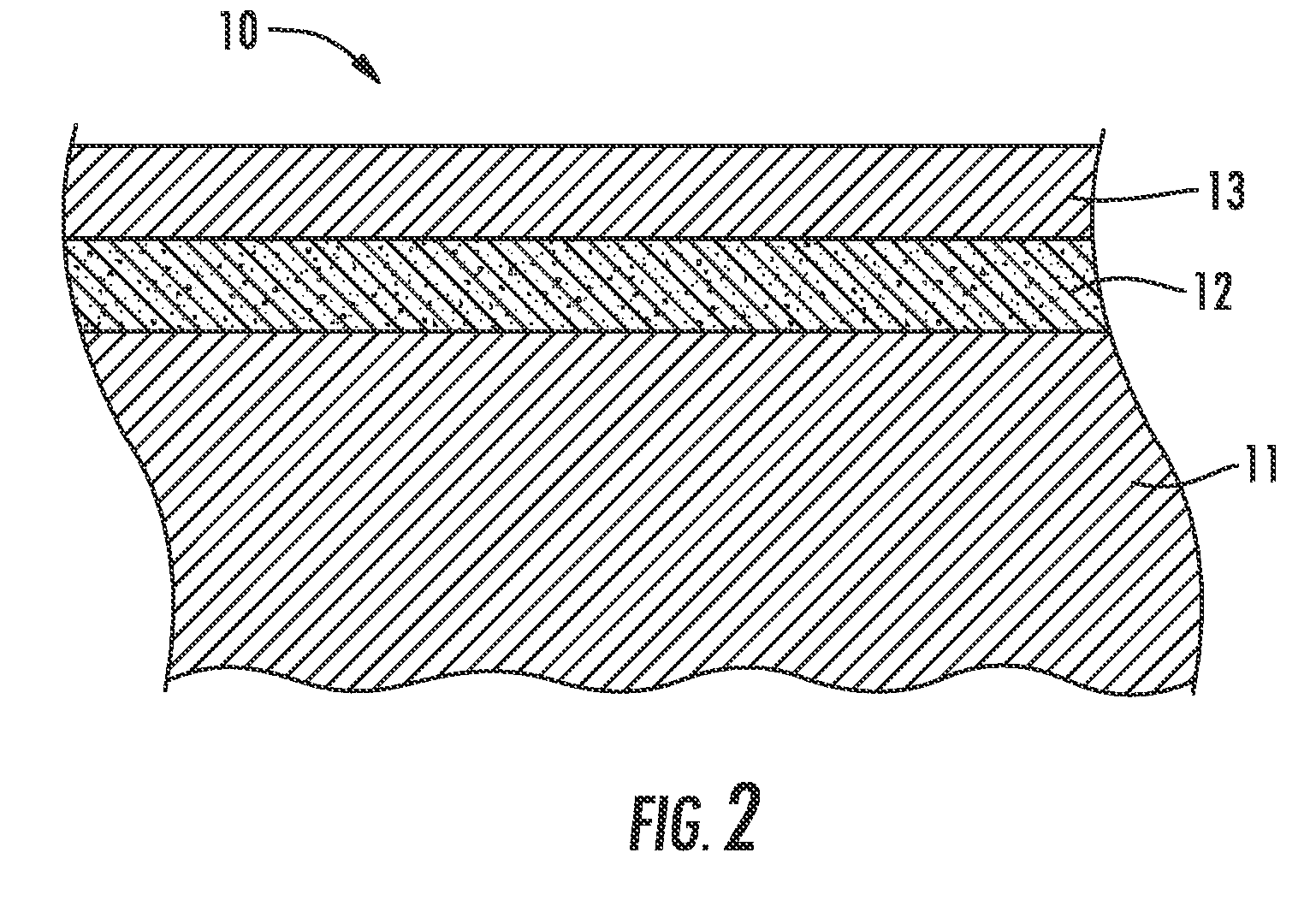
[0023]Referring initially to FIGS. 1-2, a turbine blade 10 having a bond coating 12 formed in accordance with the present invention is now described. The turbine blade 10 comprises a combustion turbine component substrate 11. A bond coating 12 is formed on the combustion turbine component substrate 11. A thermal barrier coating 13 is illustratively formed on the bond coating 12. It will be readily understood by those of skill in the art that the bond coati...


PUM

PropertyMeasurementUnit
thicknessaaaaaaaaaa
temperaturesaaaaaaaaaa
thicknessaaaaaaaaaa

Abstract

A combustion turbine component includes a combustion turbine component substrate and a bond coating on the combustion turbine component substrate. The bond coating may include Mn+1AXn (n=1,2,3) where M is selected from groups IIIB, IVB, VB, VIB, and VII of the periodic table of elements and mixtures thereof, where A is selected from groups IIIA, IVA, VA, and VIA of the periodic table of elements and mixtures thereof, and where X includes at least one of carbon and nitrogen. A thermal barrier coating may be on the bond coating.

Description

FIELD OF THE INVENTION[0001]The present invention relates to the field of metallurgy, and, more particularly, to bond coatings and related methods.BACKGROUND OF THE INVENTION[0002]A hot section component of a combustion turbine is routinely subjected to rigorous mechanical loading conditions at high temperatures. A thermal barrier coating is typically formed on such a substrate of the combustion turbine component to insulate it from such large and prolonged heat loads.[0003]The thermal barrier coating insulates the combustion turbine component substrate by using thermally insulating materials that can sustain an appreciable temperature difference between the substrate of the combustion turbine component and the thermal barrier coating surface. In doing so, the thermal barrier coating can allow for higher operating temperatures while limiting the thermal exposure of the combustion turbine component substrate, extending part life by reducing thermal fatigue.[0004]Such a thermal barrie...

Claims


Application Information

Patent Timeline
Patent Type & Authority Patents(United States)
IPC IPC(8): B32B9/00B32B15/00B32B19/00
CPCC23C4/06F01D5/284Y10T428/12493
Inventor BRINLEY, ERIK R.
Owner SIEMENS ENERGY INC
Learn More