Ion exchange membrane electrolytic cell

a technology of electrolysis cell and membrane, which is applied in the direction of electrolysis process, electrolysis components, cells, etc., can solve the problems of increasing voltage and consuming a great deal of energy in the chloroalkali industry, and achieves long-term stable operation, prevents the application of superfluous pressure, and prevents the generation of scratches

Active Publication Date: 2012-06-12
TOAGOSEI CO LTD +1
View PDF14 Cites 12 Cited by
  • Summary
  • Abstract
  • Description
  • Claims
  • Application Information

AI Technical Summary

Benefits of technology

[0033]As described, the repulsive force (resilience) of the cushion material accommodated in the cathode gas chamber of the two-chamber electrolytic cell becomes smaller toward the top part in accordance with the differential pressure between the anode chamber pressure and the cathode gas chamber pressure, thereby preventing the application of the superfluous pressure on the ion exchange membrane, preventing the generation of scratches and providing the long-term stable operation. Further, the reduction of the amount of the cushion material, or of the precious materials such as silver and nickel can be attained.

Problems solved by technology

The chloroalkali industry consumes a great deal of energy.
An insufficient repulsive force separates the anode from the ion exchange membrane and the entire gas diffusion electrode, thereby elevating the voltage.

Method used


Image

  • Ion exchange membrane electrolytic cell
  • Ion exchange membrane electrolytic cell
  • Ion exchange membrane electrolytic cell

Examples


example 1

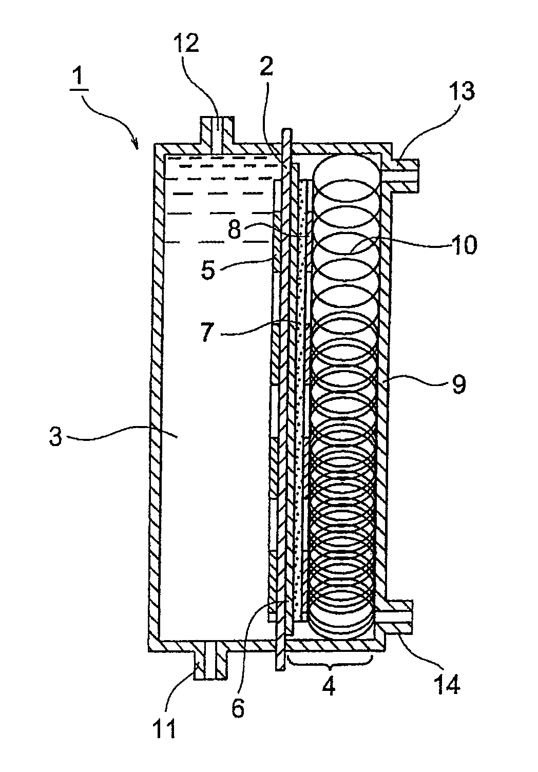
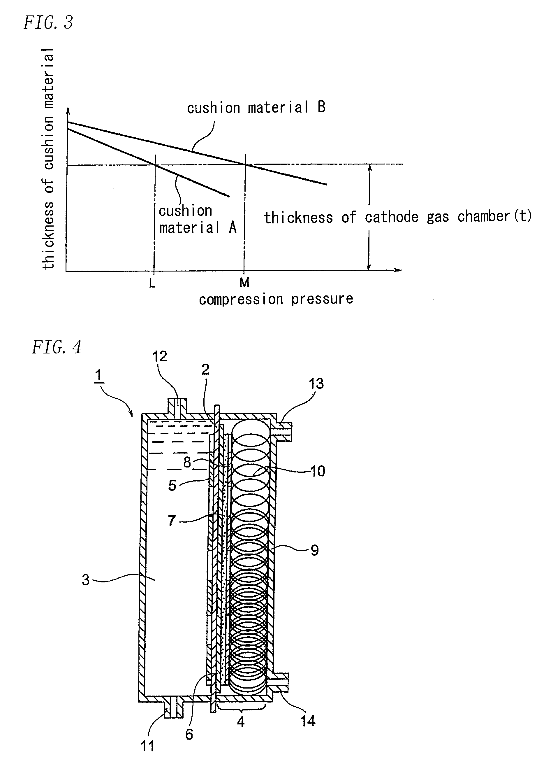
[0056]A two-chamber ion exchange membrane electrolytic cell of which an effective surface area was a width of 100 mm and a height of 1200 mm was assembled as shown in FIG. 4.

[0057]An anode used was a dimensionally stable electrode available from Permelec Electrode, Ltd., and a cathode used was a liquid permeable gas diffusion electrode. The gas diffusion electrode was prepared by impregnating, with silver fine particles and PTFE fine particles, a substrate made of nickel foam electrically plated with silver, followed by hot-pressing. The respective reaction surface sizes were 100 mm in width and 1200 mm in height.

[0058]An ion exchange membrane used was Aciplex F4203 available from Asahi Kasei Chemicals Corporation, and a liquid retention layer used was a carbon cloth having thickness of 0.4 mm available from Zoltek Companies, Inc. which was then hydrophilically treated. A gas diffusion electrode support used was a plain-weaved nickel mesh of 24 mesh which was plated with silver.

[005...

example 2

[0064]A similar test was conducted to Example 1 except that a demister mesh was employed as the cushion material.

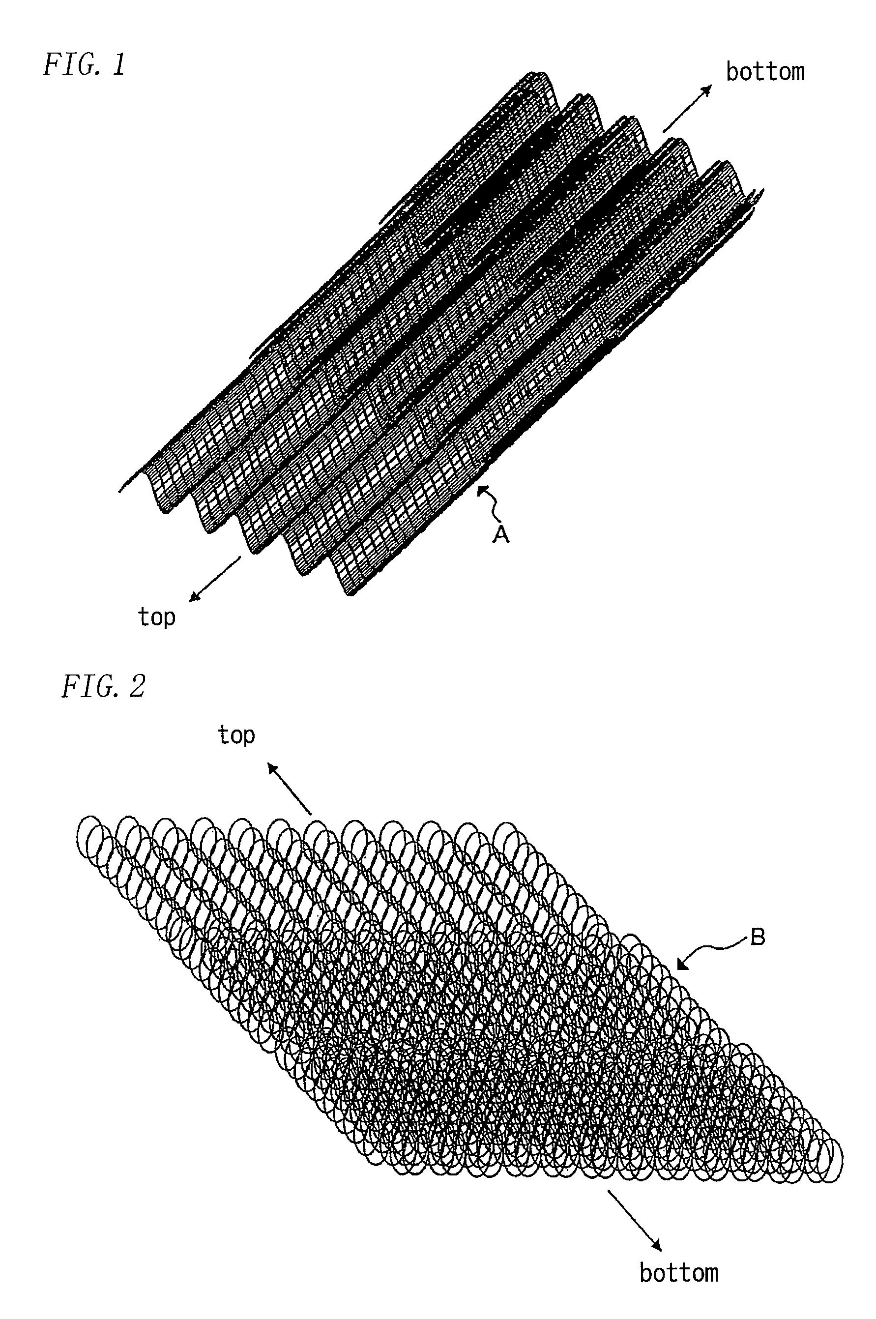
[0065]The demister meshes were prepared by knitting nickel wires having wire diameter of 0.25 mm and a pitch of 5 mm in stockinet and processing the meshes to wavy shape having depth of 5 mm and a pitch of 10 mm followed by the electric plating of silver. An amount of the plated silver was 0.5 g / mesh.dm2. When four sheets, five sheets and six sheets of the above meshes were stacked and compressed to 5.5 mm, the repulsive forces of the stacks were 7, 11 and 15 kPa, respectively. The four demister meshes were disposed on the top one-third of the cathode gas chamber, the five demister meshes were disposed on the central one-third of the cathode gas chamber, and the six demister meshes were disposed on the bottom one-third of the cathode gas chamber. The difference between the repulsive force and the liquid pressure at the respective depth direction was 2.6 kPa in minimum and...


PUM

PropertyMeasurementUnit
pressureaaaaaaaaaa
pressureaaaaaaaaaa
pressureaaaaaaaaaa

Abstract

[Problems] The liquid pressure of an anode chamber in a two-chamber ion exchange membrane electrolytic cell using a gas diffusion electrode are different among one another depending on depths so that the liquid pressures are applied on an anode or an ion exchange membrane, thereby introducing damage or deformation of the elements.[Means for Solving] A cushion material 10 is accommodated between a cathode gas chamber back plate 9 and a gas diffusion electrode 7 of an ion exchange membrane electrolytic cell 1 such that a repulsive force of the cushion material at the bottom part of the cathode gas chamber is larger than that at the top part. The excessive pressure applied to an ion exchange membrane is suppressed to prevent the generation of scratches or the like by decreasing the repulsive force of the cushion material toward the top in accordance with a differential pressure between an anode chamber pressure and a cathode gas chamber pressure.

Description

TECHNICAL FIELD[0001]The present invention relates to an ion exchange membrane electrolytic cell, and in particular to the two-chamber ion exchange membrane electrolytic cell using a gas diffusion electrode.BACKGROUND OF INVENTION[0002]Currently, brine is electrolyzed to produce hydroxide and chlorine by employing a so-called ion exchange membrane method (refer to the below formula (1)). While its theoretical decomposition voltage is about 2.25 V, the operation is practically conducted at about 3 V due to the ohmic potential drop and the overpotential of an electrode existing in the system.2NaCl+2H2O→Cl2+2NaOH+H2  (1)[0003]The chloroalkali industry consumes a great deal of energy. Accordingly, for significant energy saving, a method is investigated which includes a reaction in which a gas diffusion electrode is used as a cathode to reduce oxygen (refer to the below equation (2), and the reaction will be hereinafter referred to as “oxygen cathode method”).2NaCl+½O2+H2O→Cl2+2NaOH  (2)...

Claims


Application Information

Patent Timeline
Patent Type & Authority Patents(United States)
IPC IPC(8): C25B9/06C25B9/08C25B1/46C25B11/03C25B9/17C25B9/19C25B9/23
CPCC25B1/46C25B11/035C25B9/08C25B9/04C25B9/65C25B11/031C25B9/19
Inventor SAIKI, KOJIASAUMI, KIYOHITOHAMAMORI, MITSUHARUOSAKABE, TSUGIYOSHI
Owner TOAGOSEI CO LTD
Why Eureka
Try Eureka