Heat radiator and power module

a technology of heat radiator and power module, which is applied in the direction of final product manufacturing, sustainable manufacturing/processing, and semiconductor/solid-state device details. it can solve the problems of increasing material cost, affecting heat radiation performance, and cracking of insulating substrates, so as to improve heat radiation performance and prevent cracking. , excellent thermal conductivity

Inactive Publication Date: 2012-06-12
TOYOTA IND CORP +1
View PDF53 Cites 28 Cited by
  • Summary
  • Abstract
  • Description
  • Claims
  • Application Information

AI Technical Summary

Benefits of technology

[0026]According to the heat radiator of par. 1), the stress relaxation member formed of a high-thermal-conduction material intervenes between the insulating substrate and the heat sink and comprises a plate-like body and a plurality of projections formed at intervals on at least one side of the plate-like body, and the stress relaxation member is metal-bonded to the insulating substrate and to the heat sink. Thus, excellent thermal conductivity is established between the insulating substrate and the heat sink, thereby improving heat radiation performance for radiating heat generated by a semiconductor device mounted on the heat-generating-element-mounting side of the insulating substrate. Furthermore, even when thermal stress arises in the heat radiator from a difference in coefficient of linear thermal expansion between the insulating substrate and the heat sink, the projections of the stress relaxation member are deformed, thereby relaxing the thermal stress and thus preventing cracking in the insulating substrate, cracking in a bond zone between the insulating substrate and the stress relaxation member, and warpage of the surface of the heat sink located on a side toward the insulating substrate. Accordingly, heat radiation performance is maintained over a long term. Also, since the stress relaxation member comprises the plate-like body and the plurality of projections formed at intervals on at least one side of the plate-like body, cost of the stress relaxation member becomes relatively low, thereby lowering material cost for the heat radiator.
[0027]According to the heat radiator of par. 2), the plurality of projections are formed on only one side of the plate-like body of the stress relaxation member, and either a side of the plate-like body of the stress relaxation member on which the projections are not formed or end faces of the projections are metal-bonded to the insulating substrate, whereas the side of the plate-like body of the stress relaxation member on which the projections are not formed or the end faces of the projections, whichever are not metal-bonded to the insulating substrate, is metal-bonded to the heat sink. Thus, excellent thermal conductivity is established between the insulating substrate and the heat sink, thereby improving heat radiation performance for radiating heat generated by a semiconductor device mounted on the heat-generating-element-mounting side of the insulating substrate. Furthermore, even when thermal stress arises in the heat radiator from a difference in coefficient of linear thermal expansion between the insulating substrate and the heat sink, the projections of the stress relaxation member are deformed, thereby relaxing the thermal stress and thus preventing cracking in the insulating substrate, cracking in a bond zone between the insulating substrate and the stress relaxation member, and warpage of the surface of the heat sink located on a side toward the insulating substrate. Accordingly, heat radiation performance is maintained over a long term. Also, since the stress relaxation member comprises the plate-like body and the plurality of projections formed on only one side of the plate-like body, cost of the stress relaxation member becomes relatively low, thereby lowering material cost for the heat radiator.
[0028]According to the heat radiator of par. 3), since employment of the thermal-conduction plate increases the area of heat transfer between the insulating substrate and heat sink, thermal conductivity between the insulating substrate and the heat sink is further enhanced, thereby improving heat radiation performance for radiating heat generated by a semiconductor device mounted on the heat-generating-element-mounting side of the insulating substrate. Furthermore, even when thermal stress arises in the heat radiator from a difference in coefficient of linear thermal expansion between the insulating substrate and the heat sink, by virtue of the through-holes, the thermal-conduction plate is deformed, thereby relaxing the thermal stress.
[0029]According to the heat radiator of par. 4), since employment of the two stress relaxation members increases the area of heat transfer between the insulating substrate and heat sink, thermal conductivity between the insulating substrate and the heat sink is further enhanced, thereby improving heat radiation performance for radiating heat generated by a semiconductor device mounted on the heat-generating-element-mounting side of the insulating substrate. Furthermore, even when thermal stress arises in the heat radiator from a difference in coefficient of linear thermal expansion between the insulating substrate and the heat sink, the projections of the two stress relaxation members are deformed, thereby relaxing the thermal stress and thus preventing cracking in the insulating substrate, cracking in a bond zone between the insulating substrate and the stress relaxation member, and warpage of the surface of the heat sink located on a side toward the insulating substrate.
[0030]According to the heat radiator of par. 7) or 8), when thermal stress arises in the heat radiator, the degree of deformation of the projections is large. Thus, even when relatively high thermal stress arises in the heat radiator, the thermal stress can be relaxed.
[0031]In the case of the heat radiator of par. 9) or 10), when thermal stress arises in the heat radiator, the degree of deformation of the projections is small. However, in the case where thermal stress arising in the heat radiator is relatively low, the thermal stress can be sufficiently relaxed.

Problems solved by technology

Under some working conditions, thermal stress arises from a difference in coefficient of linear thermal expansion between the insulating substrate and the heat sink and causes cracking in the insulating substrate, cracking in a solder layer which bonds the insulating substrate and the heat sink together, or warpage of a bond surface of the heat sink bonded to the insulating substrate.
Such cracking or warpage impairs heat radiation performance.
However, the heat radiator described in Patent Document 1 must use the heat radiation member formed of a high-thermal-conduction material and a low-thermal-expansion material; thus, material cost is increased.
Furthermore, since the heat radiation member and the heat sink are merely screwed together, thermal conduction therebetween is insufficient, resulting in a failure to provide sufficient heat radiation performance.Patent Document 1: Japanese Patent Application Laid-Open (kokai) No. 2004-153075

Method used


Image

  • Heat radiator and power module
  • Heat radiator and power module
  • Heat radiator and power module

Examples


embodiment 1

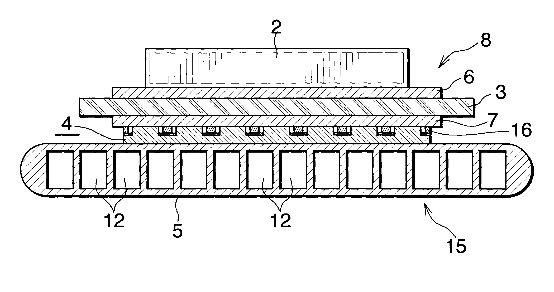
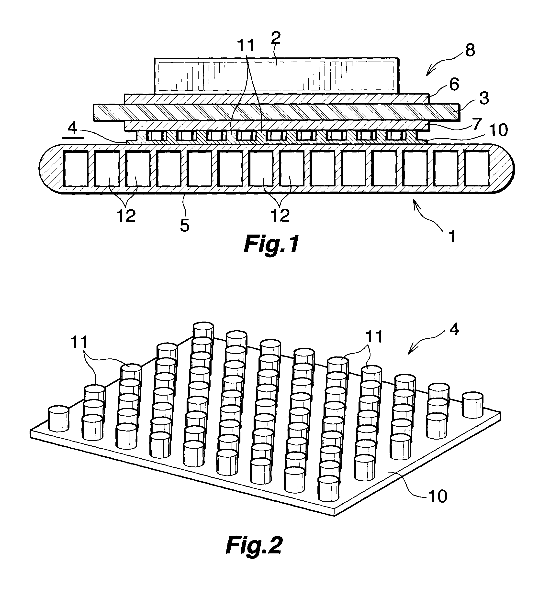
[0035]The present embodiment is shown in FIGS. 1 and 2.

[0036]FIG. 1 shows a portion of a power module which uses a heat radiator of Embodiment 1. FIG. 2 shows a stress relaxation member of the heat radiator of Embodiment 1.

[0037]In FIG. 1, the power module includes a heat radiator 1 and a semiconductor device 2; for example, an IGBT, mounted on the heat radiator 1.

[0038]The heat radiator 1 includes an insulating substrate 3 whose upper surface serves as a heat-generating-element-mounting side; a stress relaxation member 4 bonded to the lower surface of the insulating substrate 3; and a heat sink 5 bonded to the lower surface of the stress relaxation member 4.

[0039]The insulating substrate 3 may be formed of any insulating material, so long as it satisfies requirements for insulating characteristics, thermal conductivity, and mechanical strength. For example, when a ceramic is used to form the insulating substrate 3, aluminum oxide or aluminum nitride is used. A circuit layer 6 is fo...

embodiment 2

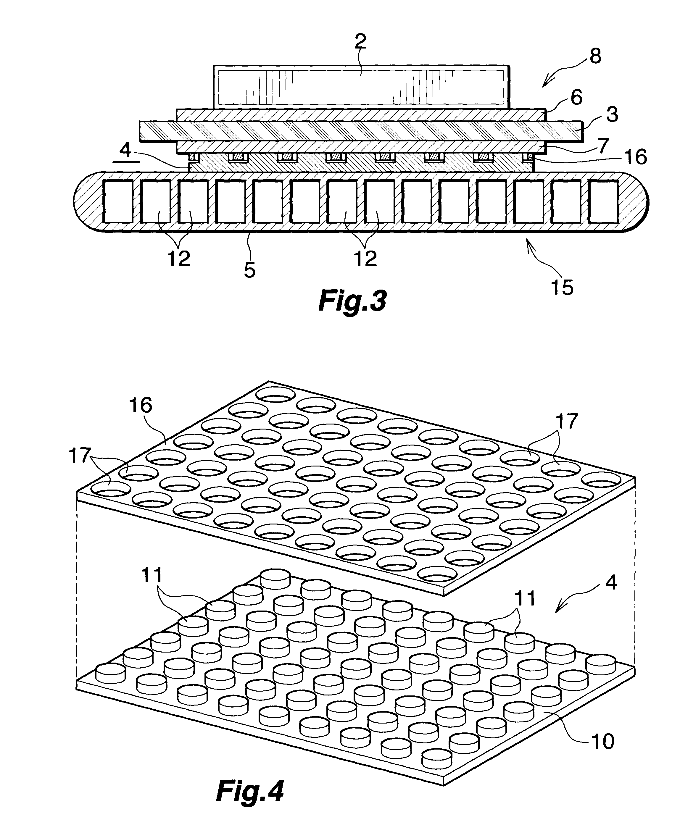
[0050]The present embodiment is shown in FIGS. 3 and 4.

[0051]FIG. 3 shows a portion of a power module which uses a heat radiator of Embodiment 2. FIG. 4 shows a stress relaxation member of the heat radiator of Embodiment 2.

[0052]In FIGS. 3 and 4, the stress relaxation member 4 similar in constitution to that of Embodiment 1, and a thermal-conduction plate 16 formed of a high-thermal-conduction material; herein, aluminum, and having a plurality of through-holes 17 allowing the respective projections 11 of the stress relaxation member 4 to extend therethrough are disposed between the power module substrate 8 and the heat sink 5 in a heat radiator 15. In Embodiment 2, the projections 11 of the stress relaxation member 4 are not formed in a staggered arrangement, but are formed in a grid arrangement. The thermal-conduction plate 16 is disposed above the plate-like body 10 of the stress relaxation member 4 in such a manner that the projections 11 extend through the respective through-hol...

embodiment 3

[0057]The present embodiment is shown in FIGS. 5 and 6.

[0058]FIG. 5 shows a portion of a power module which uses a heat radiator of Embodiment 3. FIG. 6 shows a stress relaxation member of the heat radiator of Embodiment 3.

[0059]In FIGS. 5 and 6, two stress relaxation members 4 similar in constitution to that of Embodiment 1 are disposed between the power module substrate 8 and the heat sink 5 in a heat radiator 20. The upper stress relaxation member 4 is disposed with the projections 11 facing downward, and the lower stress relaxation member 4 is disposed with the projections 11 facing upward. In Embodiment 3, the projections 11 of the two stress relaxation members 4 are not formed in a staggered arrangement, but are formed in a grid arrangement. The upper surface of the plate-like body 10 of the upper stress relaxation member 4 is brazed to the metal layer 7 of the power module substrate 8, and the lower surface of the plate-like body 10 of the lower stress relaxation member 4 is ...


PUM


Abstract

A heat radiator 1 includes an insulating substrate 3 whose first side serves as a heat-generating-element-mounting side, and a heat sink 5 fixed to a second side of the insulating substrate 3. A metal layer 7 is formed on the second side of the insulating substrate 3 opposite the heat-generating-element-mounting side. A stress relaxation member 4 formed of a high-thermal-conduction material intervenes between the metal layer 7 of the insulating substrate 3 and the heat sink 5 and includes a plate-like body 10 and a plurality of projections 11 formed at intervals on one side of the plate-like body 10. The end faces of the projections 11 of the stress relaxation member 4 are brazed to the metal layer 7, whereas the side of the plate-like body 10 on which the projections 11 are not formed is brazed to the heat sink 5. This heat radiator 1 is low in material cost and exhibits excellent heat radiation performance.

Description

TECHNICAL FIELD[0001]The present invention relates to a heat radiator, and more particularly to a heat radiator which includes an insulating substrate whose first side serves as a heat-generating-element-mounting side, and a heat sink fixed to a second side of the insulating substrate and which radiates, from the heat sink, heat generated from a heat-generating member, such as a semiconductor device, mounted on the insulating substrate.[0002]The term “aluminum” as used herein and in the appended claims encompasses aluminum alloys in addition to pure aluminum, except for the case where “pure aluminum” is specified.BACKGROUND ART[0003]In a power module which uses a semiconductor device, such as an IGBT (Insulated Gate Bipolar Transistor), the semiconductor device must be held at a predetermined temperature or lower by means of efficiently radiating heat generated therefrom. Conventionally, in order to meet the requirement, a heat radiator is used. The heat radiator includes an insulat...

Claims


Application Information

Patent Timeline
Patent Type & Authority Patents(United States)
IPC IPC(8): H05K1/00
CPCH01L23/367H01L23/3677H01L23/3735H05K3/0061H05K3/341H01L23/473H05K1/0306H01L2924/0002H05K2201/0373H05K2201/1028H05K2203/0405H01L2924/00Y02P70/50H01L23/36
Inventor OTOSHI, KOTAKONO, EIJITOH, KEIJITANAKA, KATSUFUMIFURUKAWA, YUICHIYAMAUCHI, SHINOBUHOSHINO, RYOICHIWAKABAYASHI, NOBUHIRONAKAGAWA, SHINTARO
Owner TOYOTA IND CORP
Why Eureka
Try Eureka