Assistance device for transient acceleration and deceleration phases
a technology of acceleration and deceleration phase, applied in the direction of engine starter, turbine/propulsion engine ignition, electric generator control, etc., can solve the problems of limited acceleration capacity of such a turbine engine, the effect of reducing the surge margin of turbine engine, reducing the excess flow rate of fuel needed for acceleration, and small surge margin
- Summary
- Abstract
- Description
- Claims
- Application Information
AI Technical Summary
Benefits of technology
Problems solved by technology
Method used
Image
Examples
first embodiment
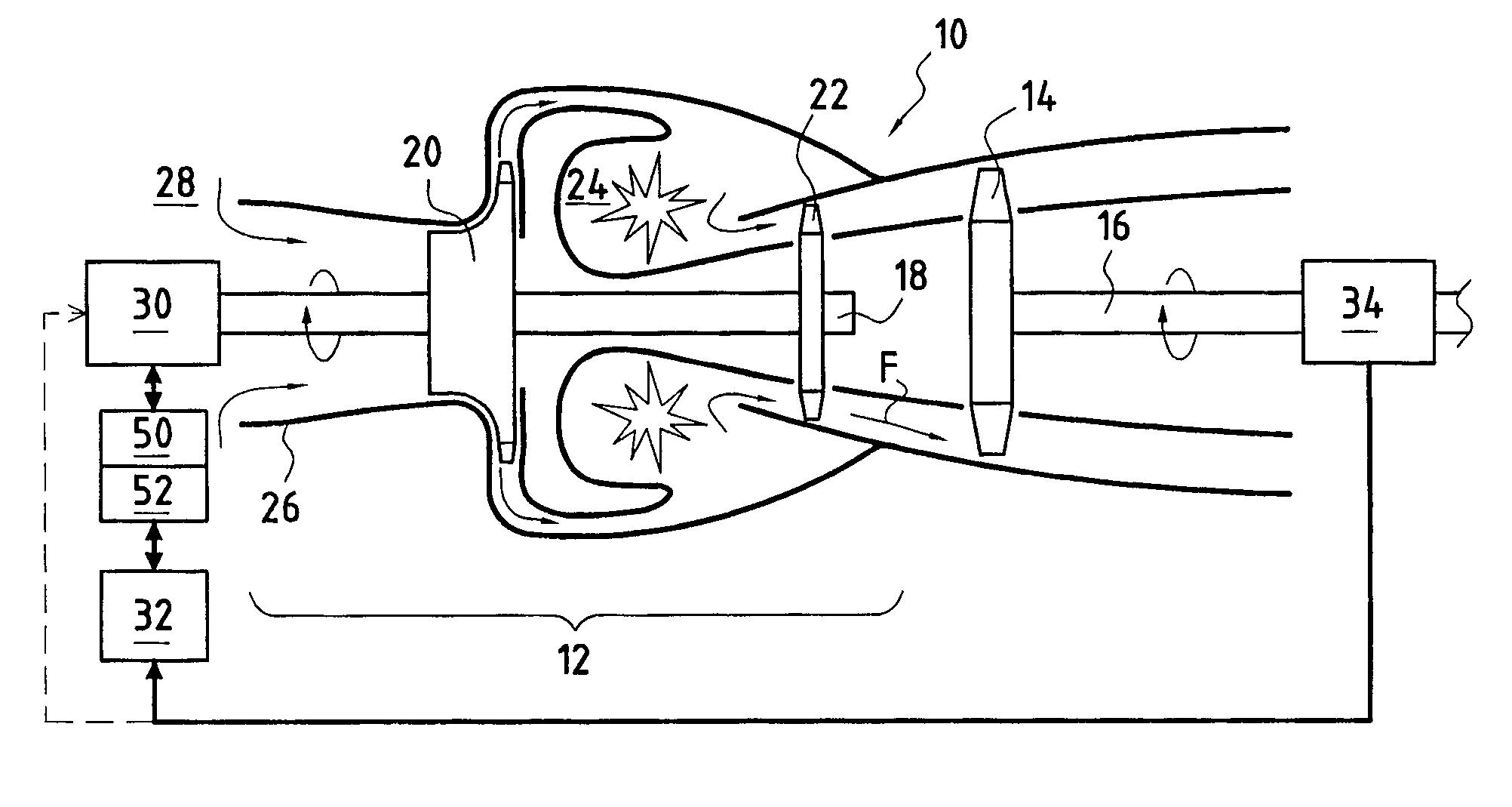
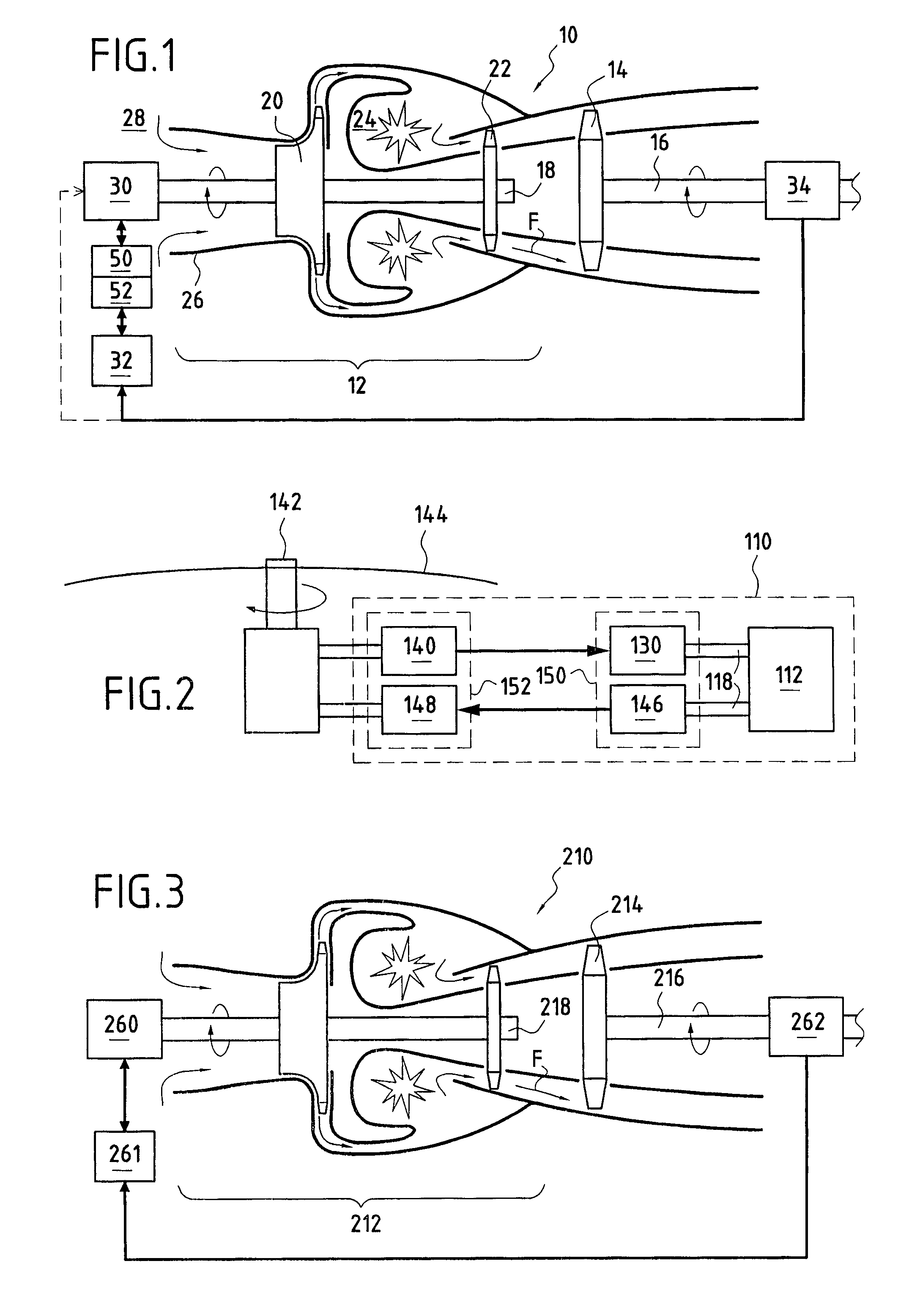
[0057]FIG. 1, is a diagram showing a turbine engine 10 constituting the invention and intended in particular to drive a helicopter rotor (not shown) in rotation, the turbine engine 10 comprising a gas generator 12 and a free turbine 14 capable of being driven in rotation by a gas flow F generated by the gas generator 12.
[0058]The free turbine 14 is mounted on a shaft 16 that transmits the rotary motion to a receiver unit such as the main rotor of the helicopter.
[0059]The turbine engine 10 shown in FIG. 1 is of the rear take-off type. Without going beyond the ambit of the present invention, it is possible to consider a turbine engine with a free turbine of the front take-off type with transfer by an outer shaft, or a turbine engine with a free turbine of the front take-off type with transfer by a coaxial shaft.
[0060]The gas generator includes a rotary shaft 18 on which there are mounted a centrifugal compressor 20, a turbine 22, and a combustion chamber 24 placed axially between the ...
second embodiment
[0086]In this second embodiment, the turbine engine 110 advantageously includes a first auxiliary electric motor 130 that is capable of delivering a quantity of additional energy to the shaft 118 of the gas generator 112.
[0087]The first electric motor 130 is advantageously powered by a first electricity generator 140 that is coupled to a shaft 142 of the rotor 144 of a helicopter in which the turbine engine 110, is mounted with the shaft 142 of the rotor 144 being coupled to the shaft of the free turbine of the turbine engine 110.
[0088]In other words, a quantity of rotational kinetic energy is drawn from the rotor 144 and transformed into electrical energy by means of the first electricity generator 140.
[0089]Obviously it is ensured that the quantity of energy that is drawn off is considerably less than the rotational kinetic energy of the rotor 144, and this does not pose any particular problems because of the high level of the kinetic energy of the rotor.
[0090]Thus, in the inventi...
third embodiment
[0095]a turbine engine 210 in accordance with the present invention is described below with reference to FIG. 3.
[0096]In this figure, any element that is identical to an element shown in FIG. 1 has the same numerical reference plus 200.
[0097]Similarly to the first embodiment, the turbine engine 210 comprises a gas generator 212 provided with a shaft 218 and a free turbine 214 having a shaft 216.
[0098]In accordance with the invention, the turbine engine 210 comprises a hydraulic auxiliary motor 260 coupled to a shaft 218 of the gas generator 212, which motor is intended to provide a quantity of rotational kinetic energy to the shaft 218 of the gas generator 212 during a stage of turbine engine acceleration 212.
[0099]This motor 260 may be powered by a hydraulic source placed in the helicopter, e.g. by a first pump 262 coupled to a shaft 216 of the free turbine 214, or any other storage device, preferably a hydraulic pressure accumulator 261.
[0100]In this embodiment, the turbine engine...
PUM
 Abstract
Description
Claims
Application Information
 - R&D
- Intellectual Property
- Life Sciences
- Materials
- Tech Scout
- Unparalleled Data Quality
- Higher Quality Content
- 60% Fewer Hallucinations
Browse by: Latest US Patents, China's latest patents, Technical Efficacy Thesaurus, Application Domain, Technology Topic, Popular Technical Reports.
© 2025 PatSnap. All rights reserved.Legal|Privacy policy|Modern Slavery Act Transparency Statement|Sitemap|About US| Contact US: help@patsnap.com


