Magnetorheological force transmission device

a transmission device and magnetorheological force technology, applied in the direction of spring/damper design characteristics, vibration dampers, mechanical devices, etc., can solve the problems of adopting a minimum damping force and known devices not showing an advantageous fail-safe behavior, and achieve a greater degree of freedom and better fail-safe behavior

Inactive Publication Date: 2012-06-26
FRAUNHOFER GESELLSCHAFT ZUR FOERDERUNG DER ANGEWANDTEN FORSCHUNG EV
View PDF17 Cites 6 Cited by
  • Summary
  • Abstract
  • Description
  • Claims
  • Application Information

AI Technical Summary

Benefits of technology

[0003]It is thus one object of the present invention to provide magnetorheological force transmission devices which provide a larger degree of freedom wi...

Problems solved by technology

Magnetorheological force transmission devices of this kind, however, have the disadvantage that when the energy supply fails, the device (espe...

Method used


Image

  • Magnetorheological force transmission device
  • Magnetorheological force transmission device
  • Magnetorheological force transmission device

Examples


Embodiment Construction

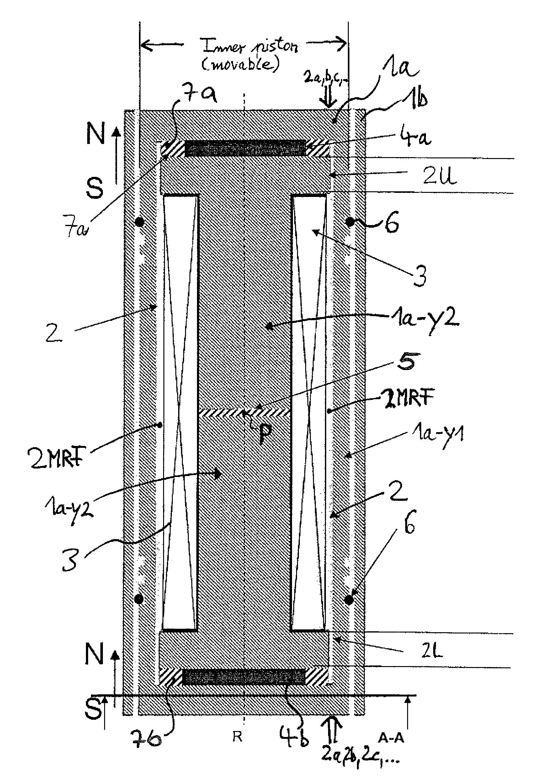
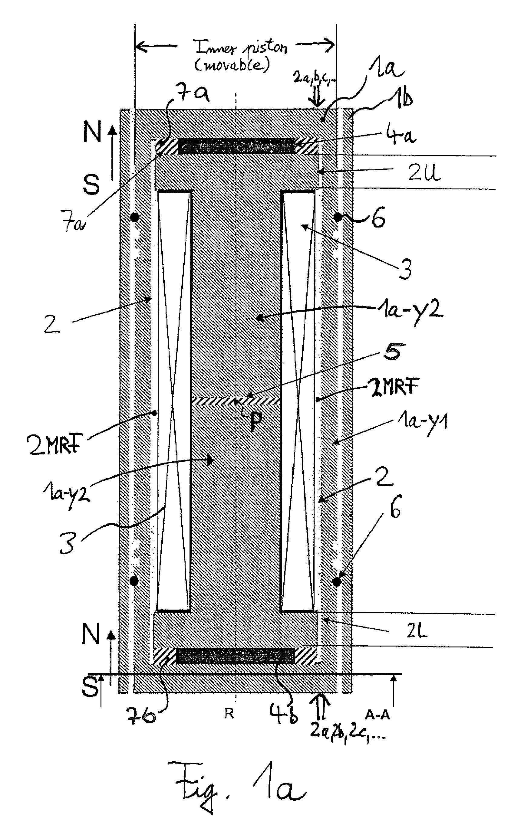
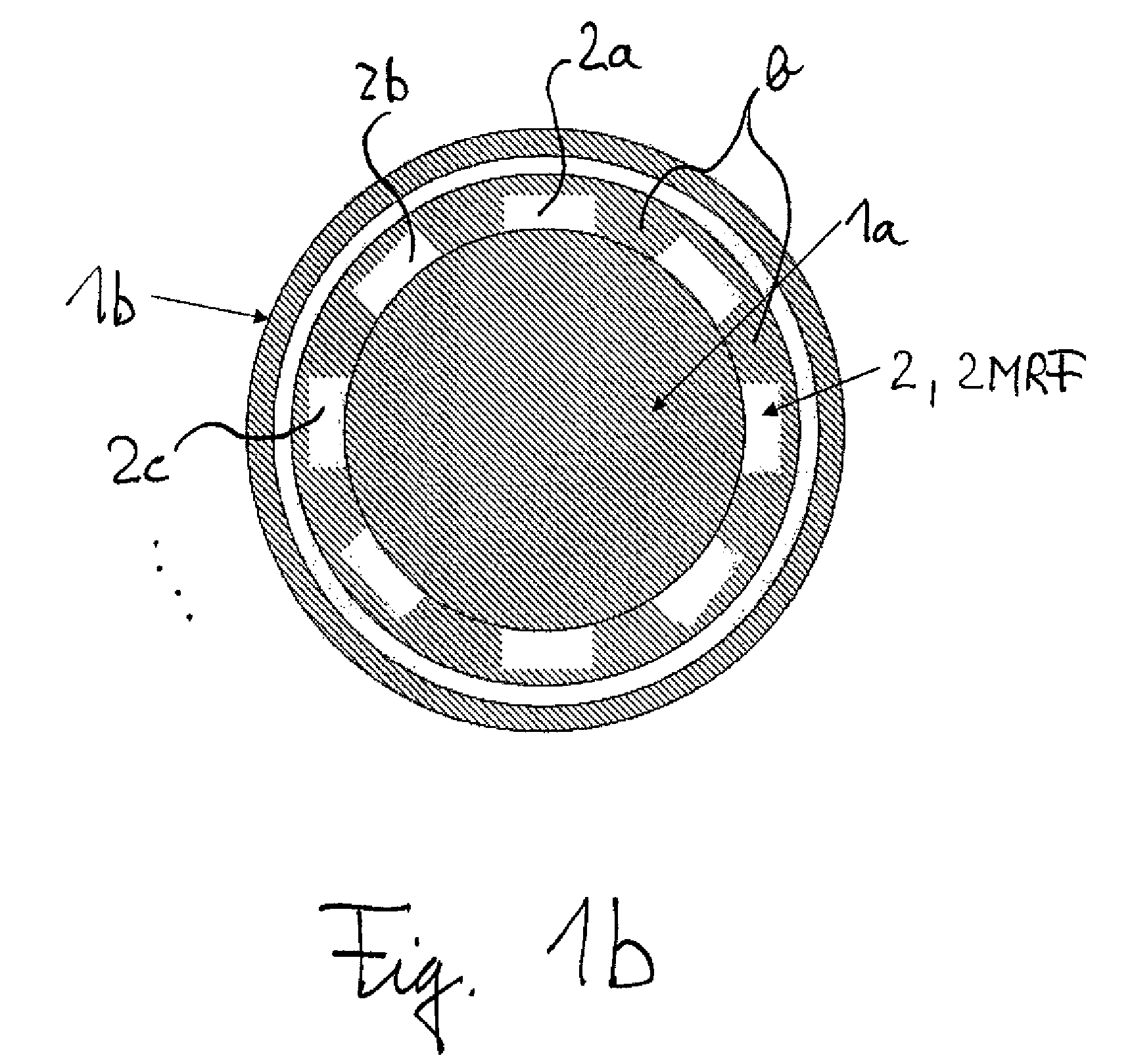
[0024]FIG. 1a shows a sectional view (through the central, longitudinal axis of the shown device) of a magnetorheological force transmission device according to the present invention, which constitutes a shock absorber. FIG. 1b shows a cross-section through the shown device along the direction A-A in FIG. 1a, i.e. perpendicular to the axis R. Basically, the shown damper comprises two piston elements: A first piston element 1a, essentially formed in form of a cylinder, which is inserted or nested in a second piston element 1b, which is formed as a hollow cylinder in which the first piston element 1a can be introduced along the longitudinal symmetry axis R of the shown device. Thus, both pistons are adapted to be moved one relative to the other in a translational manner along a common line, wherein said line is arranged essentially in parallel to the common longitudinal axis R of the two pistons or equals this common axis. The part 1a is thus slideably movable within the part 1b. Both...


PUM


Abstract

The present invention discloses a magnetorheological force transmission device which comprises at least two solid body parts adapted to be moved in a substantially translational manner against each other, and an MRF gap, which is at least partially fillable and/or filled with a magnetorheological material 2MRF, the MRF gap being arranged at least partially inside one of or both of the two parts and/or being arranged at least partially in-between the two parts, and which is characterized in that the magnetic circuit system of the magnetorheological force transmission device being designed and/or disposed to generate a magnetic flux within at least part of the MRF gap comprises at least one electromagnet, at least one permanent magnet and at least one magnetic-field-balancing insert and/or magnetic isolator.

Description

BACKGROUND[0001]The present invention relates to a magnetorheological force transmission device and to several embodiments thereof, e.g. in form of dampers, locking devices, blocking devices and safety switches as well as to uses thereof and to magnetorheological force transmission methods.[0002]Magnetorheological force transmission devices are already known, see e.g. EP 1 270 988 B1 or DE 101 43 980 A1. The known magnetorheological force transmission devices generate the magnetic field based on electromagnets in the form of coils. Magnetorheological force transmission devices of this kind, however, have the disadvantage that when the energy supply fails, the device (especially in form of a damper) adopts a state of minimum damping force. This means that the known devices do not show an advantageous fail-safe behavior.SUMMARY OF THE INVENTION[0003]It is thus one object of the present invention to provide magnetorheological force transmission devices which provide a larger degree of ...

Claims


Application Information

Patent Timeline
IPC IPC(8): F16F9/53
CPCF16F9/535F16F2230/24
Inventor BOSE, HOLGEREHRLICH, JOHANNESMENEROUD, PATRICKMAGNAC, GREGORY
Owner FRAUNHOFER GESELLSCHAFT ZUR FOERDERUNG DER ANGEWANDTEN FORSCHUNG EV
Why Eureka
Try Eureka