Non-imaging diffuse light concentrator

a concentrator and diffuse light technology, applied in the field of solar energy, can solve the problems of reducing the direct sunlight collected, haze or smog, and the cost of flat-panel solar electric collectors, and achieve the effects of increasing concentratio, reducing the size of the receiver, and high concentration ratio

Inactive Publication Date: 2012-06-26
ROSA JAMES
View PDF1 Cites 7 Cited by
  • Summary
  • Abstract
  • Description
  • Claims
  • Application Information

AI Technical Summary

Benefits of technology

[0005]This invention is radiant energy trap. It comprises a refractor that is positioned to be incident with radiant energy reflected off at least one reflector. The refractor is shaped and positioned to direct radiant energy to a receiver. The refractor substantially comprises a prism shape. The receiver is interfaced with the refractor. The invention is a diffuse and direct radiant energy concentrator that can have of a solid angle of acceptance (AOA) of ambient radiant energy, equivalent to that of a flat panel solar collector. The AOA is achieved while maintaining a relatively high concentration ratio (CR) of diffuse light that significantly reduces the size of the receiver. The refractor can employ combinations of different refractive index materials (I-of-R) and take advantage of total internal reflection (TIR). The refractor can be solid or a composite of nested layers. Refractive layers can increase concentration ratio and reduce thermal losses. Inner fluid refractive layers can be thermal transfer fluid, flowing through the invention. The refractor can be symmetrical or asymmetrical, have transparent and some reflective surfaces. The receiver can have functions such as a thermal receiver, a detector or transducer. The receiver can have flat opposing faces to support the use of bi-facial photoelectric (PV) cells. The reflector(s) can be simple or a composite of different curvatures that are symmetrical or asymmetrical. The simple collector geometry permits high optical and thermal efficiency. The invention can have a relatively low profile, low RL / A, and be a higher CR 3-D concentrator, without lowering AOA or collector array packing density. Installed system payback period is reduced to a minimum. The different embodiments allow for cost effective optimization. The invention can replace stationary flat panel solar collectors, some parabolic concentrators, or be a secondary concentrator to multiply a primary CR or to simplify tracking requirements.

Problems solved by technology

Flat panel solar electric (PV cell) collectors are relatively expensive.
Even haze or smog reduce the direct sunlight collected.
Significant costs are incurred for critical reflector shape, support structure, sun tracking capability, and transmission loss to less sunny regions.
Flat panel PV cell collectors are simple to construct, can be stationary and hemi-spherically collect ambient radiant energy, however they operates less efficiently with diffuse only light.
The main problem with prior art is that they suffer from a relatively small AOA, or too low a diffuse light CR-AOA combination.
Installed system payback periods are too long to be generally accepted.
In seasonal climates, providing most of a buildings thermal and electrical needs would require an unreasonably large un-shaded solar collector area.
These designs have small AOA for the CR, poor energy utilization, require sun tracking or are cost prohibitive relative to the current invention.

Method used


Image

  • Non-imaging diffuse light concentrator
  • Non-imaging diffuse light concentrator
  • Non-imaging diffuse light concentrator

Examples


embodiment 28

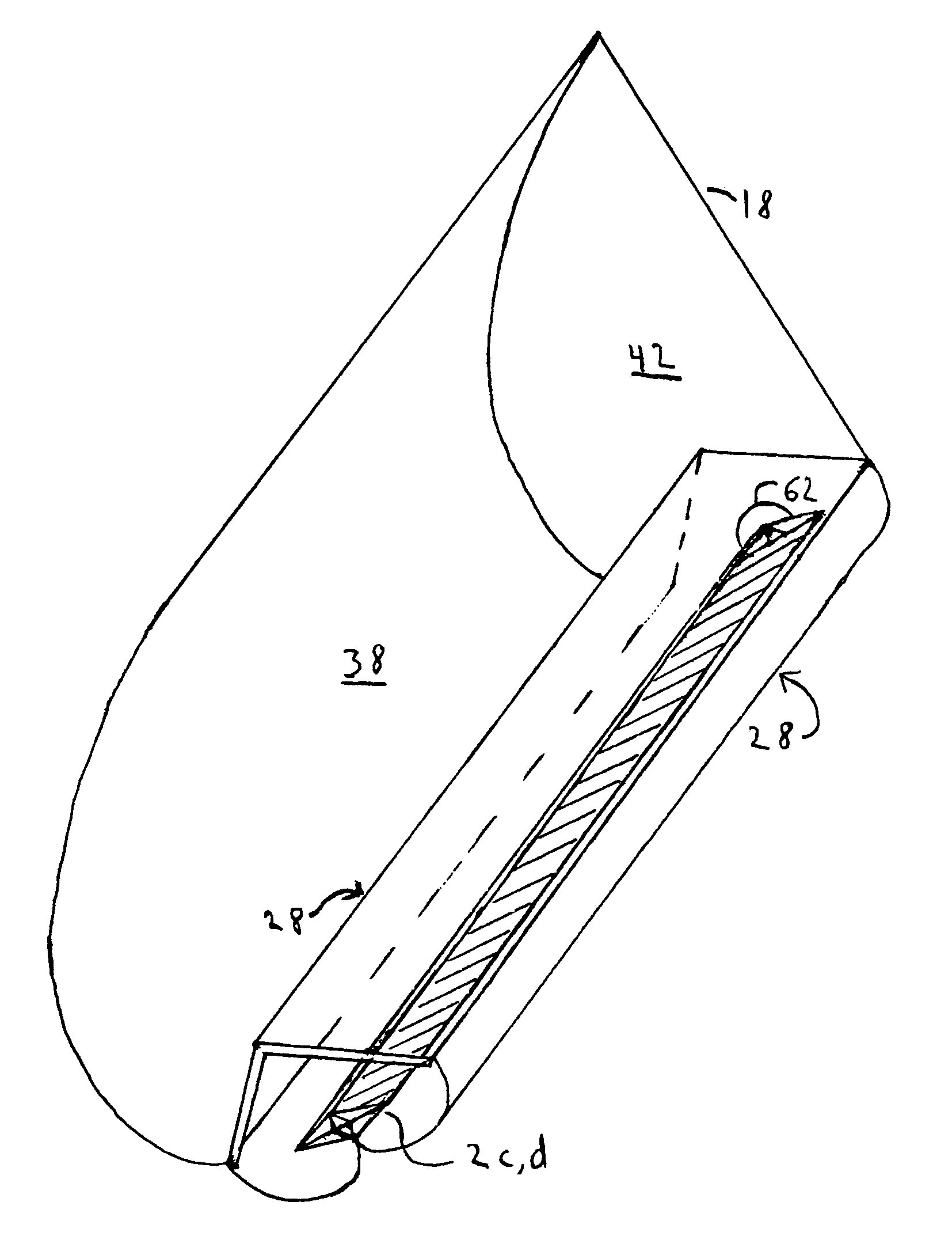
[0033]FIG. 9 is a perspective view of FIG. 8 extended longitudinally in the third dimension. It is shown as a section of trough like collector, with the asymmetrical refractor embodiment 28 of FIG. 7b, and its secondary composite refractor 2c, and 2d. The refractor 28 is adjacent to the asymmetrical reflector 38. The reflector 38 and refractor 28 are terminated with a planar reflector end cap 42 with a free edge 18. The refractor's fluid port 62 exits through the end cap 42. In FIG. 9, the planar reflector end cap 42 is in a transverse cross-section parallel to a transverse cross-section of FIG. 8.

embodiment 30

[0034]FIG. 10 is a transverse cross-sectional view of an embodiment of the invention with an asymmetrical reflector 39. FIG. 10 uses a refractor embodiment 30 that is a version of the refractor from FIG. 7c. The aperture A to receiver 1 proportion is a CR of about four. The transverse AOA 13 is about 130°. To improve thermal efficiency a transparent, thin walled, half-round tube 31 surrounds the refractor's transparent outer section 2ae. The gap32 in between the circular arc section 31 and the transparent solid outer refractor section 2ae, can be filled with a low conductance gas or be substantially evacuated. A an insulating material 35 can enclose the secondary reflector 342. The refractor 30 is proportionally about 40% solid refractor areas 2ae and 2c. The inside top 2e of the solid refractor 2ae is curved to better support a substantially evacuated gap 32.

[0035]FIG. 11 is an embodiment of the invention as a higher CR 3-D diffuse light concentrator. FIG. 11 is a perspective view ...


PUM


Abstract

A radiant energy trap. This diffuse and direct radiant energy concentrator comprises at least one reflector, a refractor substantially prism shaped and a receiver interfaced with the refractor. The invention is capable of a solid angle of acceptance of radiant energy, equivalent to that of a flat panel collector, while maintaining a relatively high concentration ratio of diffuse light. The invention can be embodied as an effective hybrid solar electric and thermal collector. A unique yet simple geometry results in relatively high optical and thermal efficiency. The invention can be embodied as a low profile 3-D diffuse light concentrator, combining reflection, refraction, and total internal reflection to approach the thermodynamic limit. It minimizes materials cost to the limits of cost reduction with relatively high efficiency PV cells. The invention increases the utilization of available solar energy and greatly reduces installed system payback periods, compared to prior art.

Description

TECHNICAL FIELD[0001]The invention is a radiant energy trap. It relates to the field of solar energy and more particularly to combined electric and thermal conversion and diffuse light concentrating solar collectors.BACKGROUND ART[0002]Problems associated with the use of fossil fuels, such as global warming, environmental degradation, rising energy costs, peak oil, and global conflicts, have created a need for a solar based economy. Cost competitive solar energy production will probably be required before this goal can be reached. Flat panel solar electric (PV cell) collectors are relatively expensive. Attempts to economize solar energy include concentrating parabolic reflectors that only work in direct sunlight. Even haze or smog reduce the direct sunlight collected. Significant costs are incurred for critical reflector shape, support structure, sun tracking capability, and transmission loss to less sunny regions. Flat panel PV cell collectors are simple to construct, can be statio...

Claims


Application Information

Patent Timeline
Patent Type & Authority Patents(United States)
IPC IPC(8): H01L31/0232F24S23/71F24S90/00
CPCF24J2/06F24J2/062F24J2/1047F24J2/18H01L31/0547G02B19/0042G02B19/0028G02B19/0076F24J2/07F24J2002/003Y02E10/52Y02E10/44F24J2002/1042Y02E10/46F24S23/80F24S23/00F24S23/79F24S20/20F24S2023/88F24S2023/838F24S23/10
Inventor ROSA, JAMES
Owner ROSA JAMES
Why Eureka
Try Eureka