
Stereo vision system and stereo vision processing method

a stereo vision and processing method technology, applied in image analysis, instruments, computing, etc., can solve the problems of slow processing speed, noisy output disparity, fast processing speed, etc., and achieve the effect of reducing power consumption and efficient power managemen

Active Publication Date: 2012-06-26
ELECTRONICS & TELECOMM RES INST
View PDF18 Cites 52 Cited by
  • Summary
  • Abstract
  • Description
  • Claims
  • Application Information

AI Technical Summary

Benefits of technology

The present invention provides a stereo vision system and method that can capture lower resolution image information through image compression and acquire high-resolution image information through stereo matching upon detection of an object. The system can also check calibration of the stereo camera and reduce power consumption by supplying power only when high-resolution image information is acquired. The technical effects of the invention include efficient power management and improved camera calibration.

Problems solved by technology

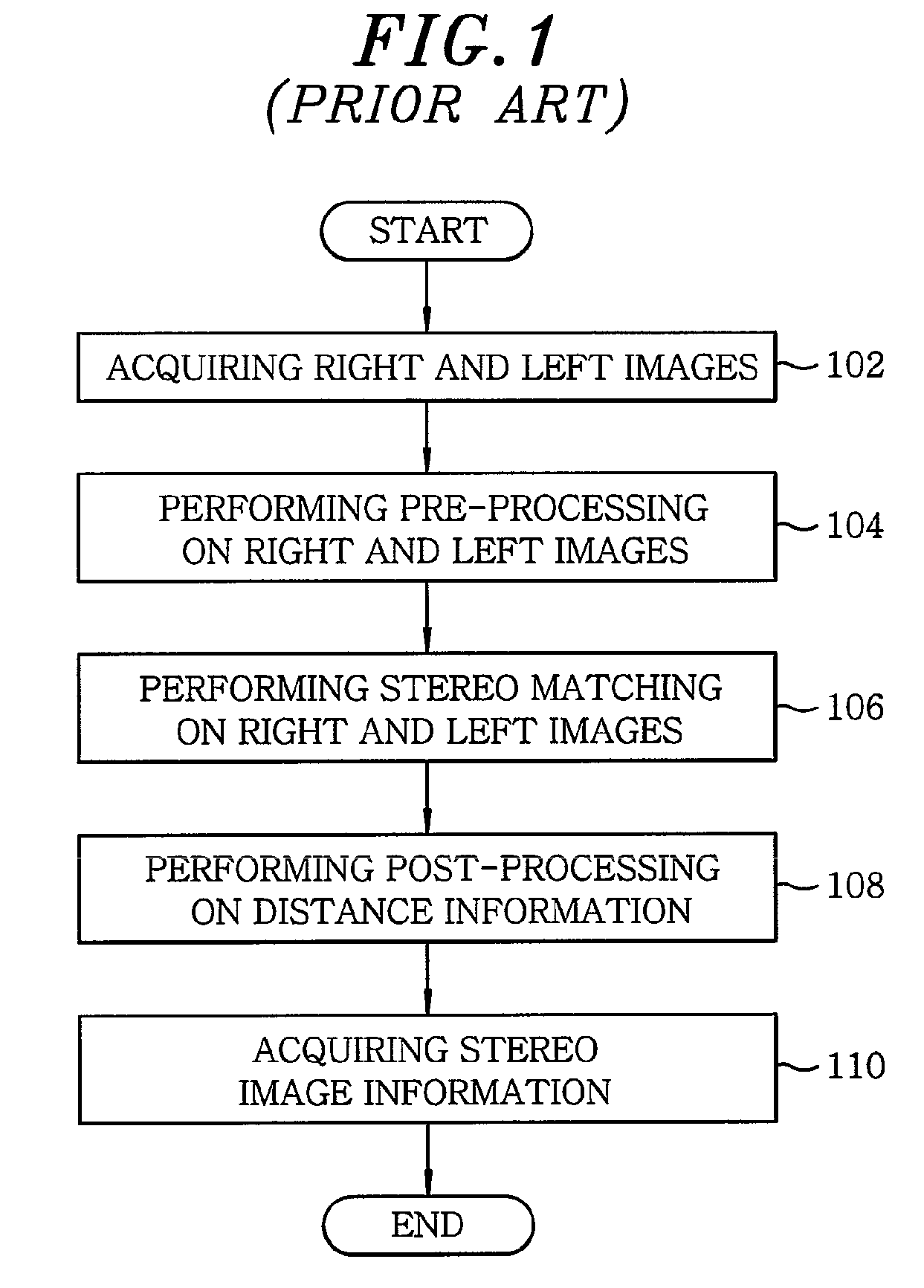
However, unlike the principle of two eyes of a person that enables acquisition of information about a distance of the center portion of an entire image, stereo matching technique requires a large number of calculations because all information about distances from the entire image are calculated, and causes noise in an output disparity because the characteristics of images acquired by two cameras generally are not completely identical with each other and there may exist a dark area or an area where a specific pattern cannot be clearly discriminated in the images.
The former may easily use various algorithms but has a slow processing speed, and the latter may use only a specific limited algorithm but has a fast processing speed.
However, since such a conventional stereo vision system runs an algorithm in a personal computer or on an FPGA and is mounted to a mobile system, e.g., a robot, it requires high cost and high power consumption.

Method used


Image

  • Stereo vision system and stereo vision processing method
  • Stereo vision system and stereo vision processing method
  • Stereo vision system and stereo vision processing method

Examples


Embodiment Construction

[0035]Hereinafter, embodiments of the present invention will be described in detail with reference to the accompanying drawings.

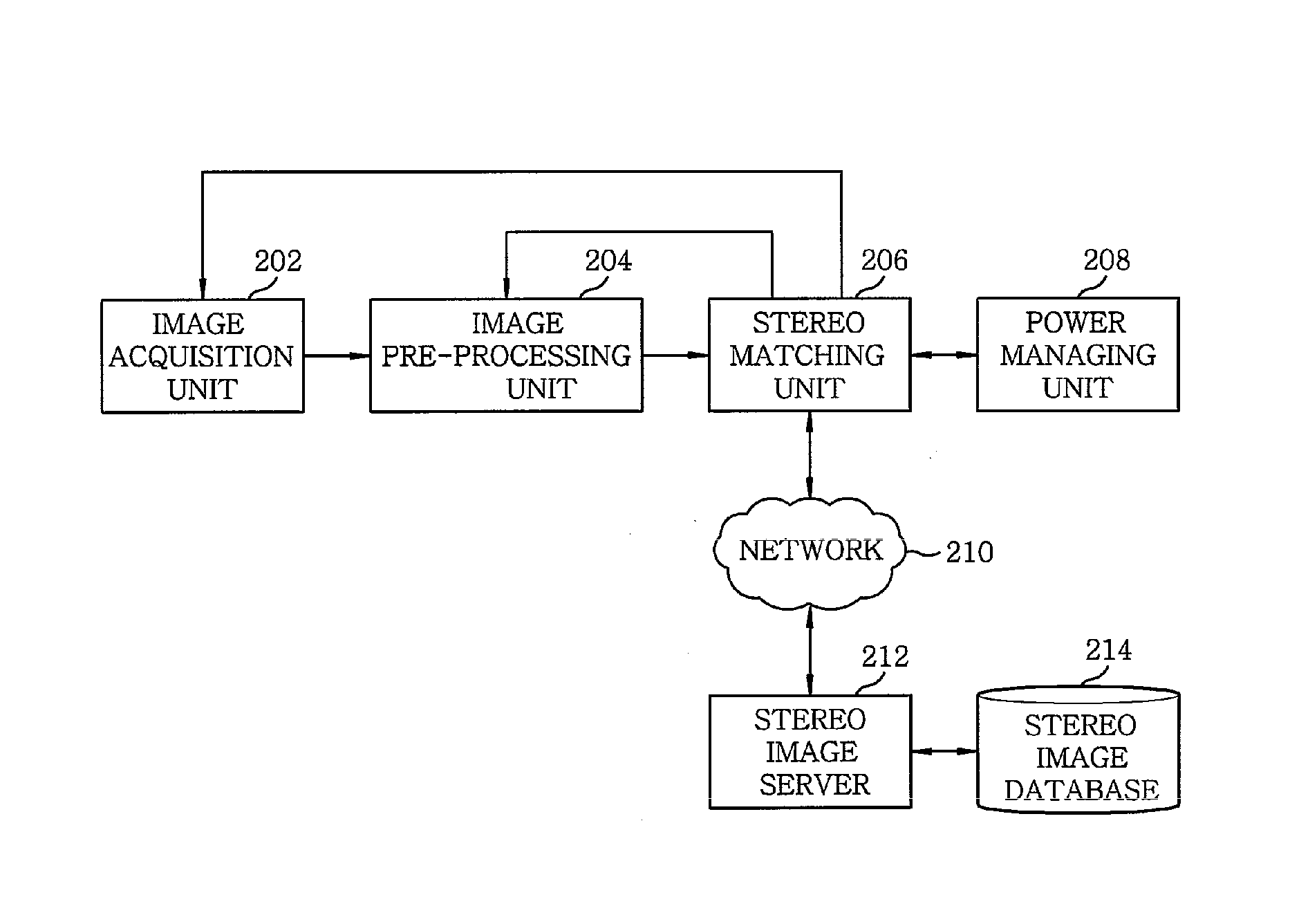
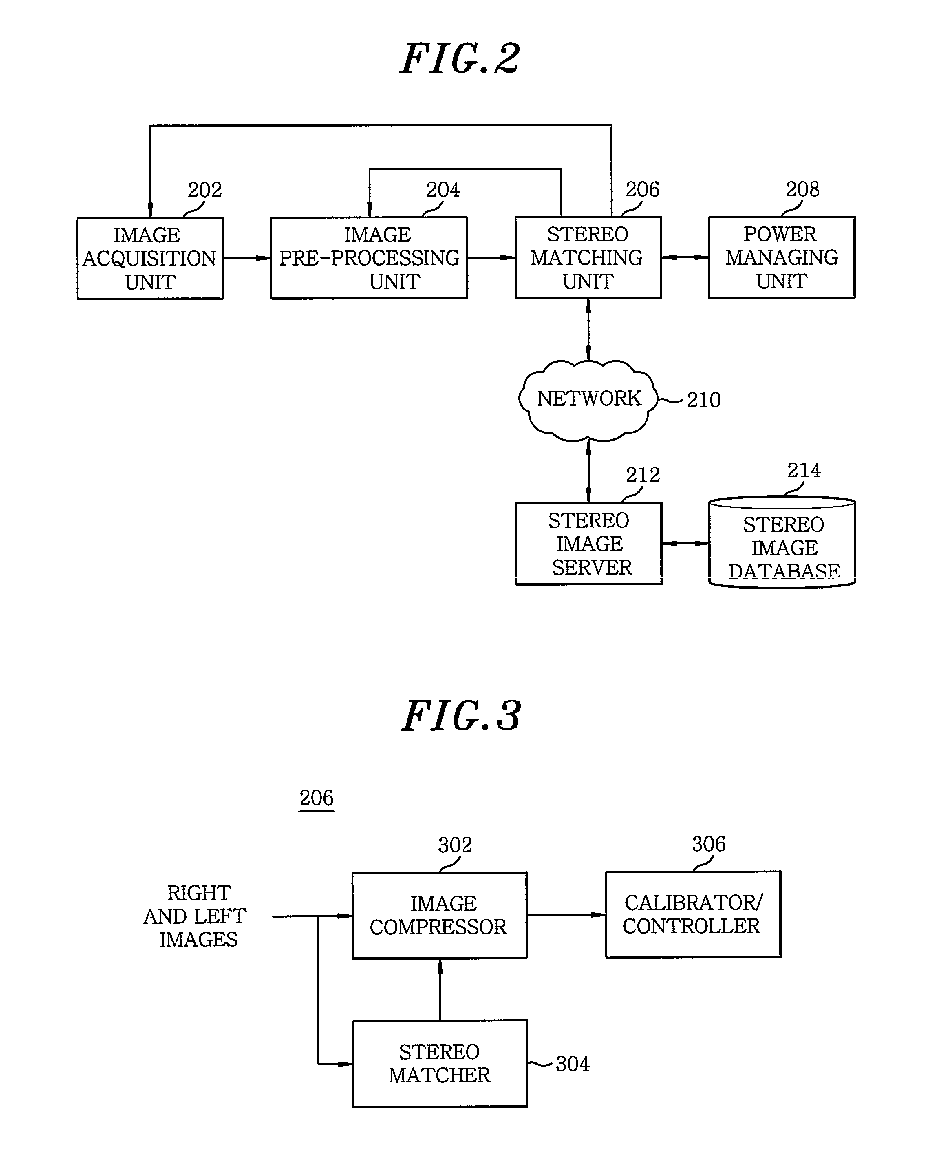
[0036]FIG. 2 is a block diagram illustrating a stereo vision system suitable for acquisition of low-resolution image information and high-resolution image information in accordance with an embodiment of the present invention. The stereo vision system includes an image acquisition unit 202, an image processing unit 204, a stereo matching unit 206, a power managing unit 208, a camera calibrating unit 210, a network 212, e.g., LAN (local area network), a stereo imager server 214, and a stereo image database 216.

[0037]With reference to FIG. 2, the image acquisition unit 202 includes a stereo camera using a charge coupled device (CCD) module or a complementary metal oxide semiconductor (CMOS) module to photograph an object through right and left lenses of the stereo camera. Photographed images, which may include moving images, are converted by the CCD module or ...


PUM


Abstract

A stereo vision system includes an image pre-processing unit for pre-processing the right and left images, and a stereo matching unit for carrying out stereo matching of the right and left images to acquire low-resolution distance information of the right and left images and high-resolution distance information of the right and left images upon detection of an object within a distance range through the low-resolution distance information.

Description

CROSS-REFERENCE(S) TO RELATED APPLICATION[0001]The present invention claims priority of Korean Patent Application No. 10-2007-0089140, filed on Sep. 3, 2007, which is incorporated herein by reference.FIELD OF THE INVENTION[0002]The present invention generally relates to a stereo vision system and, more particularly, to a stereo vision system and a stereo vision processing method suitable for acquisition of low-resolution distance information and high-resolution distance information using image compression, stereo matching, and stereo vision processing schemes.[0003]This work was supported by the IT R&D program of MIC / IITA [2005-S-033-03, Embedded Component Technology and Standardization for URC].BACKGROUND OF THE INVENTION[0004]As well known in the art, stereo matching refers to a technology of extracting 3D image information from two images produced by two cameras installed on the right and left sides. The stereo matching enables direct calculation of a distance between the locatio...

Claims


Application Information

Patent Timeline
Patent Type & Authority Patents(United States)
IPC IPC(8): G06K9/00
CPCG06T7/0075G06T7/593H04N13/00
Inventor CHOI, SEUNG MINLIM, EUL GYOONCHO, JAE ILHWANG, DAE HWAN
Owner ELECTRONICS & TELECOMM RES INST
Learn More