
Signal compression for fiber node

a fiber node and signal compression technology, applied in the field of data transmission using a cable modem, can solve the problem of requiring a lot of bandwidth, and achieve the effect of compressing bandwidth, freeing up capacity, and efficiently using the frequency spectrum of a cable network

Active Publication Date: 2012-07-03
BEIJING XIAOMI MOBILE SOFTWARE CO LTD
View PDF9 Cites 10 Cited by
  • Summary
  • Abstract
  • Description
  • Claims
  • Application Information

AI Technical Summary

Benefits of technology

The present invention is about improving the operation of cable modems by using narrow bandwidth data signals in the upstream direction to utilize unused bandwidth within the frequency spectrum. This is done by compressing the data signals to a narrower bandwidth, which allows for better use of bandwidth in fiber node systems. The use of a digital signal processor (DSP) and compression techniques, such as shaping filters or fast Fourier transform functions, makes this possible. The invention also allows for the detection and utilization of silent periods in the band, resulting in faster access to CATV network services. Overall, the invention provides a universal solution that requires minimal space and can be placed in a fiber node.

Problems solved by technology

A problem with using a fiber node 30 in a cable network is that a lot of bandwidth is required.

Method used


Image

  • Signal compression for fiber node
  • Signal compression for fiber node
  • Signal compression for fiber node

Examples


first embodiment

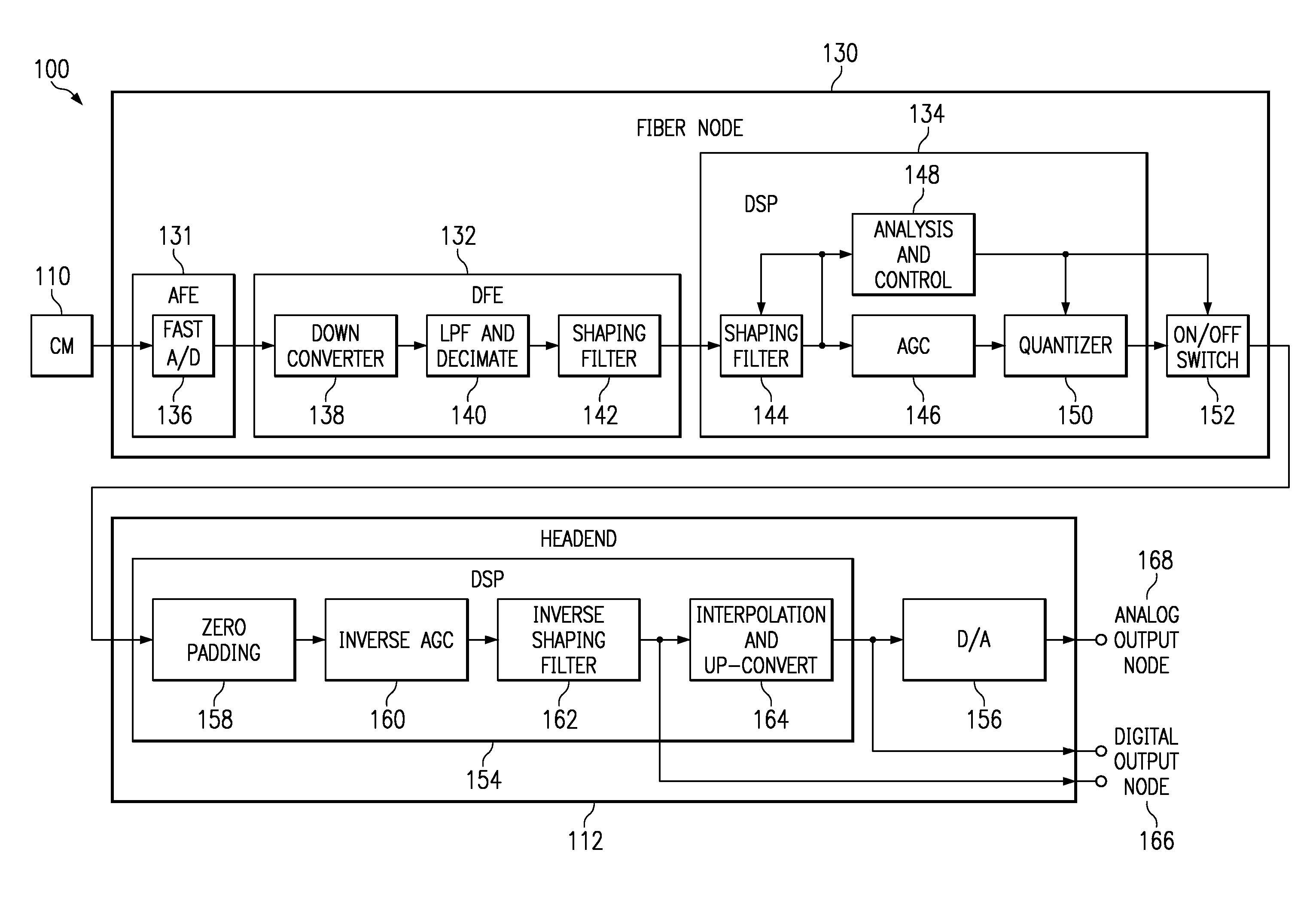
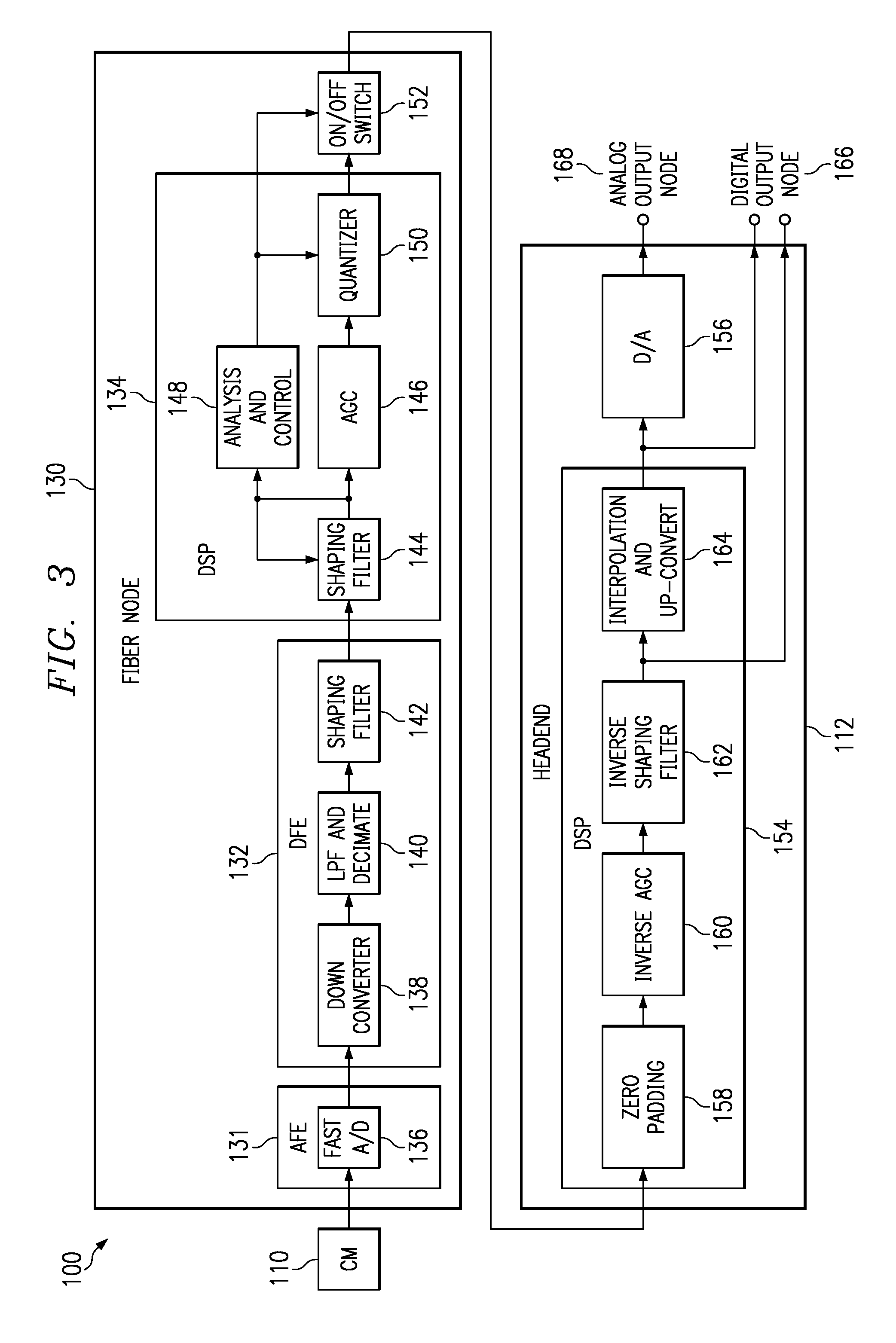
[0026]Embodiments of the present invention use data compression and IP format packaging to achieve a more efficient use of bandwidth in a CATV network. Two compression approaches in accordance with embodiments of the present invention will next be described. FIG. 3 shows generally at 100 a first embodiment having a DSP 134, 154 in a fiber node 130 and headend 112, respectively for compressing the upstream data signal bandwidth. Cable modem 110 comprises a unit located at a user's PC or other computing device and is adapted to perform modulation and demodulation, and other operations necessary to interface with the computing device. Cable modem 110 is coupled through coaxial cables or HFC in a home or other building to a fiber node 130, which may be located on a telephone pole or other remote location. Fiber node 130 is adapted to provide CATV modem service to cable modem 110. Fiber node 130 is coupled to headend 112 which is typically located in a CMTS. Headend 112 provides CATV mod...

second embodiment

[0033]FIG. 4 shows the present invention generally at 200 that employs a frequency-based approach and fast Fourier transforms to compress the upstream data signal bandwidth. Fiber node 210 comprises an AFE 231 coupled to cable modem 210. AFE 231 may comprise an amplifier, and an anti-aliasing band pass filter (BPF) (not shown) coupled to a fast A / D converter 236. AFE 231 receives an upstream analog signal from cable modem 210, amplifies it, filters it, and converts it to a digital signal.

[0034]The output of AFE 231 is coupled to the input of DFE 232. AFE 231 and DFE 232 may comprise a single IC, for example, and may comprise a 4522 chip. DFE 232 comprises a down converter 238 for down converting the digital signal received from the AFE 231. Down converter 238 is coupled to a LPF and decimater 240 adapted to filter and decimate the digital signal received from the down converter 238. An optional shaping filter 242 may be coupled to LPF and decimater 240. The DFE 232 may be modified t...


PUM


Abstract

A method, device and network for compressing cable modem data signals and conserving bandwidth within the network. Cable modems transmit upstream data signals to a fiber node which compresses the data signals and transmits the compressed signals upstream to a headend which decompresses the data signals. The fiber node compression may be by a shaping filter or a fast Fourier transform (FFT) function. The headend decompression may be by an inverse shaping filter or an inverse FFT function.

Description

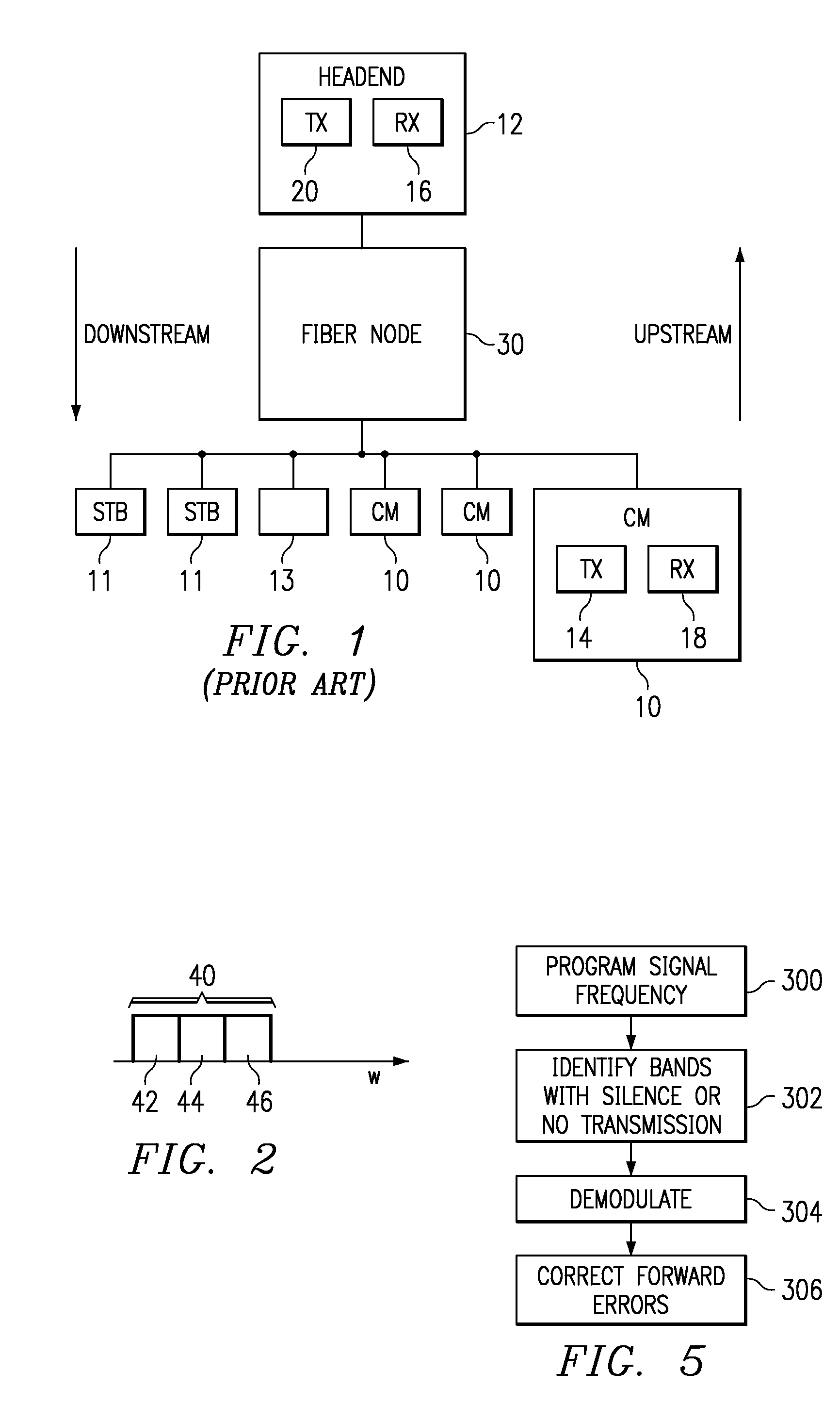
CROSS REFERENCE TO RELATED APPLICATIONS[0001]This application is a Divisional of and claims priority under 35 U.S.C. §120 to[0002]United States patent application 10 / 230,815, filed on Aug. 29, 2002 which is a non-provisional application of Application Ser. No. 60 / 317,690 filed 09 / 06 / 2001 (now abandoned).TECHNICAL FIELD[0003]This invention relates generally to communications networks, and more particularly to data transmission using a cable modem.BACKGROUND[0004]With reference to FIG. 1, cable TV (CATV) networks have utilized legacy set-top boxes (STB's) 11 for many years. Such set-top boxes are coupled via a coaxial cable to a headend 12 for cable TV service. Legacy cable telephony 13 sets can also be coupled to the cable network for information exchange.[0005]Cable modems 10 are being deployed today that allow high-speed Internet access in the home over a cable network, often referred to as a Hybrid Fiber / Coax (HFC) cable network. The architecture of a cable modem used in a cable n...

Claims


Application Information

Patent Timeline
Patent Type & Authority Patents(United States)
IPC IPC(8): H04N7/173H04N21/437H04N21/61
CPCH04N7/17309H04N21/437H04N21/615
Inventor SHALVI, OFIRSEGAL, MORDECHAI
Owner BEIJING XIAOMI MOBILE SOFTWARE CO LTD
Learn More