Electrical machine and permanent-magnet

a permanent magnet and electric motor technology, applied in the field of electric machines, can solve the problems of affecting the operation of the electric motor, and generating acoustic noise with low frequencies, and achieve the effect of increasing the efficiency of the machine, fast and effectiv

Active Publication Date: 2012-07-10
SIEMENS GAMESA RENEWABLE ENERGY AS
View PDF15 Cites 1 Cited by
  • Summary
  • Abstract
  • Description
  • Claims
  • Application Information

AI Technical Summary

Benefits of technology

[0032]an increased efficiency of the machine, . . . , etc.
[0033]Due to the Bezier-function the best compromise between magnet volume, machine efficiency, cogging torque, cogging ripple, demagnetization etc. can be found by an iterative adjustment of a few parameters only. The optimisation is thus fast and effective.
[0035]This number of constraints reduces the complexity of the iterative optimization, too.
[0037]Thus an optimized air gap flux density is provided, reducing the cogging forces between the stator and the magnet pole.

Problems solved by technology

The torque pulsations may result in vibrations, which propagates inside the machine and within a used supporting structure of the machine also.
The torque pulsations may harm mechanical and electrical components.
Furthermore the torque pulsations may generate acoustic noise with low frequencies.
The frequencies are audible and thus disturb the environment, the human-beings and the wildlife.
However this kind of chamfering does not reduce the cogging-torque and the ripple-torque to a satisfactory level.
It is very difficult and expensive to manufacture this geometry.
Even this approximation does not reduce the cogging-torque and the ripple-torque to a satisfactory level.

Method used


Image

  • Electrical machine and permanent-magnet
  • Electrical machine and permanent-magnet
  • Electrical machine and permanent-magnet

Examples


Embodiment Construction

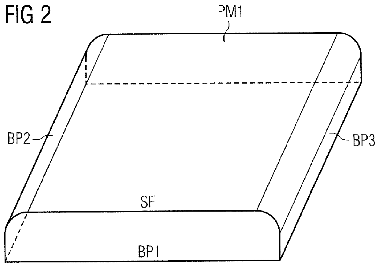
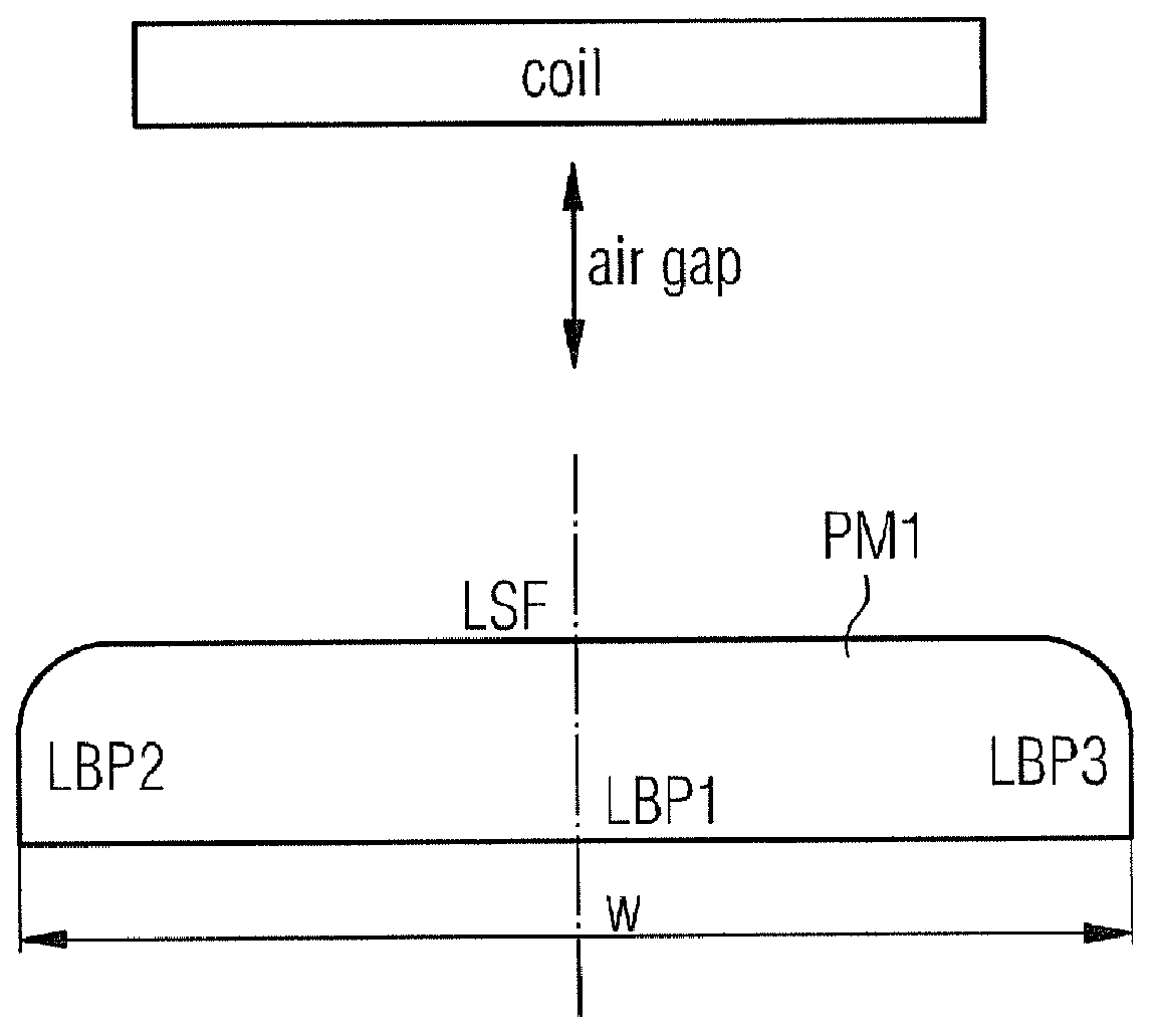
[0046]FIG. 1 shows a cross-sectional view of a permanent magnet PM1, which is shaped according to the invention.

[0047]The cross section of the permanent magnet PM1 contains three linear sections LBP1, LBP2, LBP3. These sections LBP1, LBP2, LBP3 may belong to rectangular areas BP1, BP2, BP3 as shown in FIG. 2 later.

[0048]The cross section of the permanent magnet PM1 contains also a line LSF. The line LSF is shaped according to a Bezier-function at their edges, while the edges are assigned to a transition area between the surface of the magnet and adjacent base planes as shown in FIG. 2 later.

[0049]Thus the line LSF is converted to the adjacent linear sections LBP2 and LBP3 by help of the Bezier-function or Bezier-curve.

[0050]The surface line LSF belongs to a surface SF of the permanent magnet PM1 as shown in FIG. 2 later.

[0051]The shaped surface is aligned to a coil and to an air gap, which is between the permanent magnet PM1 and the coil.

[0052]FIG. 2 shows a perspective view of the ...


PUM


Abstract

An electrical machine including a permanent magnet and a coil is provided. The coil is arranged to interact with the permanent magnet via an air gap, which located between the two. Electrical power is generated in the coil when the permanent magnet or the coil is moved in their relative position to each other. The permanent magnet includes a surface, which is aligned to the coil and to the air gap so that that magnetic forces of the permanent magnet interact via the surface and the air gap with the coil by a magnetic flux density distribution. The permanent magnet also includes a base plane and a transition area. A first side of the surface is connected with the adjacent base plane via the transition area. The cross-section of the transition between the surface and the adjacent base plane is determined by a Bezier function.

Description

CROSS REFERENCE TO RELATED APPLICATIONS[0001]This application claims priority of European Patent Office application No. 10159785.4 EP filed Apr. 13, 2010, which is incorporated by reference herein in its entirety.FIELD OF INVENTION[0002]The invention relates to an electrical machine, which contains permanent magnets and to the permanent magnets being used. The invention especially relates to a synchronous machine.BACKGROUND OF INVENTION[0003]An electrical machine like a generator contains a number of permanent magnets, which interact with at least one coil to generate electrical power. For the magnets used a compromise needs to be found. It is necessary to minimize or even avoid at least some of the following problems:[0004]First of all the magnetic force (magnetic field-strength) of the magnets will vary due to their individual characteristics and tolerances. Periodical torque pulsations will occur if the machine is within the status “no-load”, “idling” or “full load”.[0005]Next th...

Claims


Application Information

Patent Timeline
Patent Type & Authority Patents(United States)
IPC IPC(8): H02K21/12
CPCH02K1/278H02K29/03Y02E10/725Y02E10/72
Inventor THOMAS, ARWYN
Owner SIEMENS GAMESA RENEWABLE ENERGY AS
Why Eureka
Try Eureka