
Method of controlling coherent synchroton radiation-driven degradation of beam quality during bunch length compression

a beam quality and beam quality technology, applied in lasers, radiation, radiation therapy, etc., can solve the problems of beam quality degradation, prior art beam quality degradation has not been able to avoid this problem, and the beam quality is deteriorated

Inactive Publication Date: 2012-07-10
JEFFERSON SCI ASSOCS LLC
View PDF2 Cites 13 Cited by
  • Summary
  • Abstract
  • Description
  • Claims
  • Application Information

AI Technical Summary

Benefits of technology

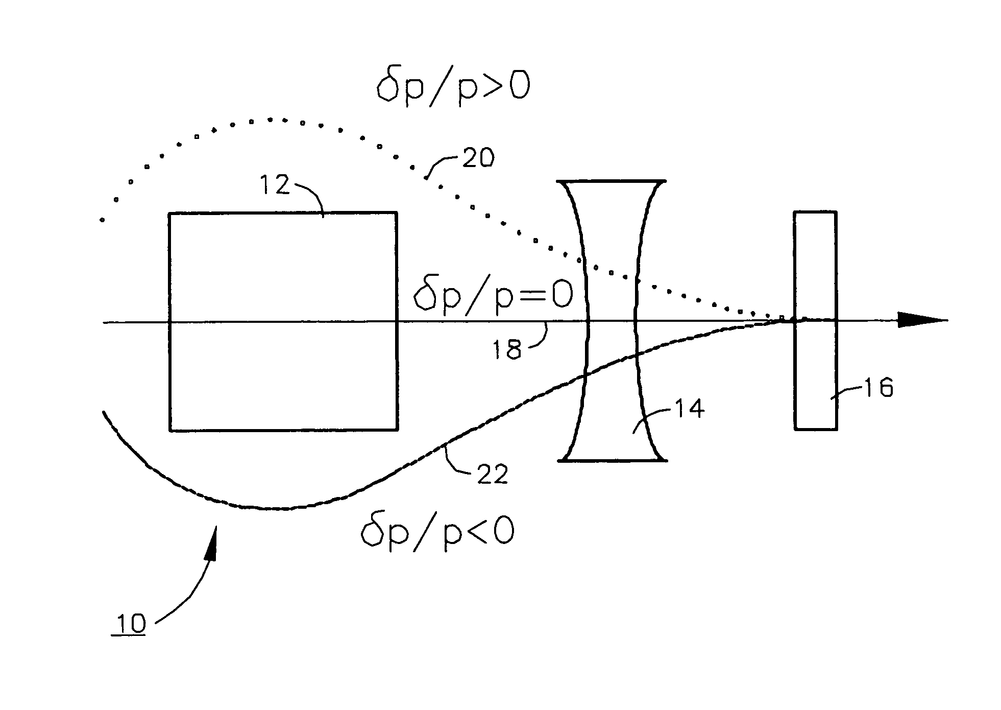
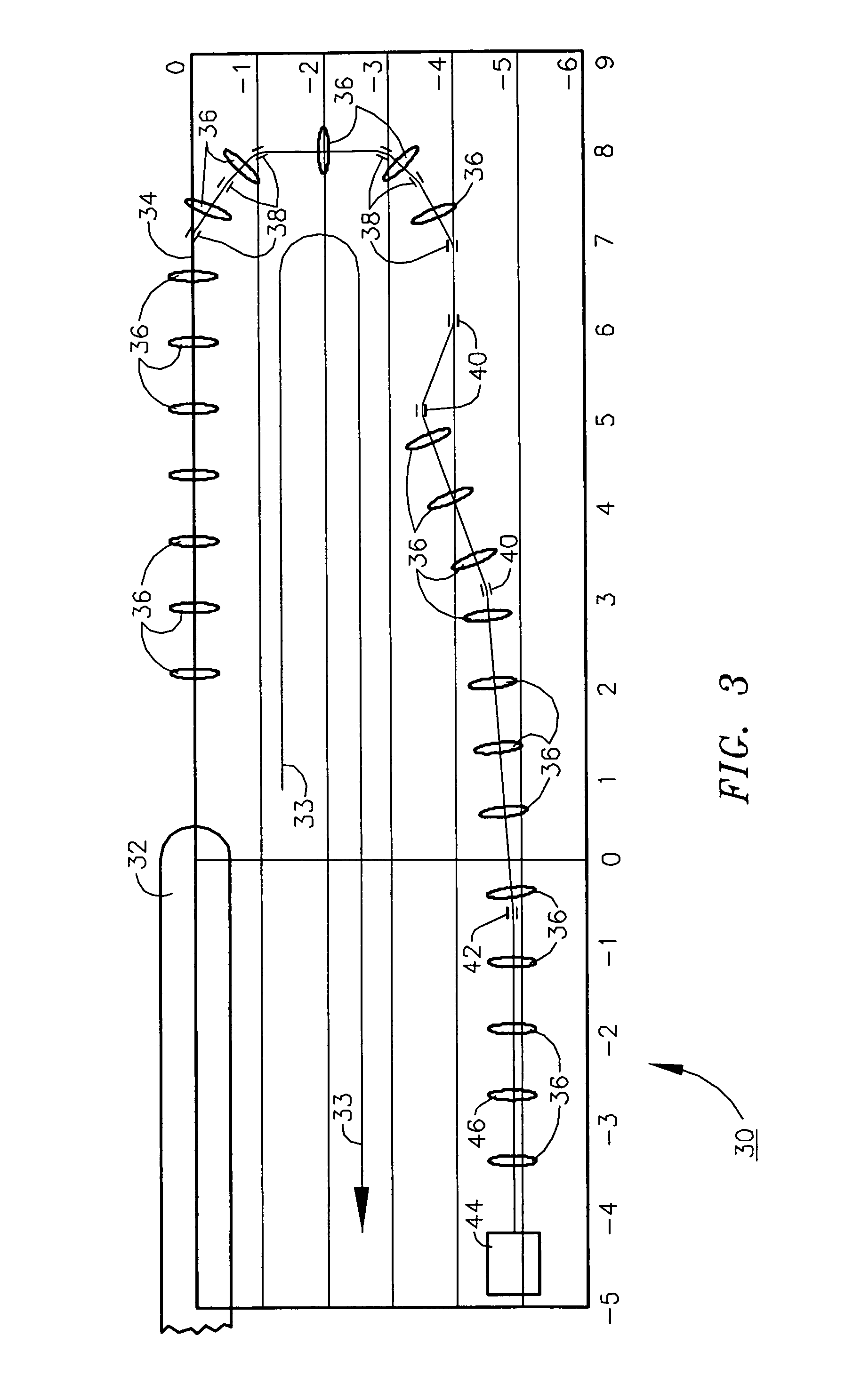
[0006]According to the present invention there is provided a method of avoiding this effect by a) controlling the rate of compression and b) using a novel means of integrating the compression with the remainder of the transport system: both are accomplished by means of dispersion modulation. A large dispersion is created in the penultimate dipole magnet of the compression region, leading to rapid compression; this large dispersion is demagnified and dispersion suppression performed in a final small dipole. As a result, the bunch is short for only a small angular extent of the transport, and the resulting CSR excitation is small.

Problems solved by technology

Coherent synchrotron radiation (CSR) drives potentially severe degradation of beam quality when compressing a bunched electron beam.
Prior art methods of bunching have been unable to avoid this problem, as all prior methods involve compressing the bunch slowly and / or traversing a large angle dipole with a short bunch.
Degradation of beam quality due to these effects limits the performance of all existing designs for energy recovery linac (ERL) drivers of free electron lasers (FELs) at single bunch charges much in excess of 100 pC.
Thus, driver transport system designs in which the beam undergoes either parasitic compressions or transport at short bunch lengths through large bend angles are incapable of maintaining beam quality adequate for lasing with high efficiency or at high power.

Method used


Image

  • Method of controlling coherent synchroton radiation-driven degradation of beam quality during bunch length compression
  • Method of controlling coherent synchroton radiation-driven degradation of beam quality during bunch length compression
  • Method of controlling coherent synchroton radiation-driven degradation of beam quality during bunch length compression

Examples


Embodiment Construction

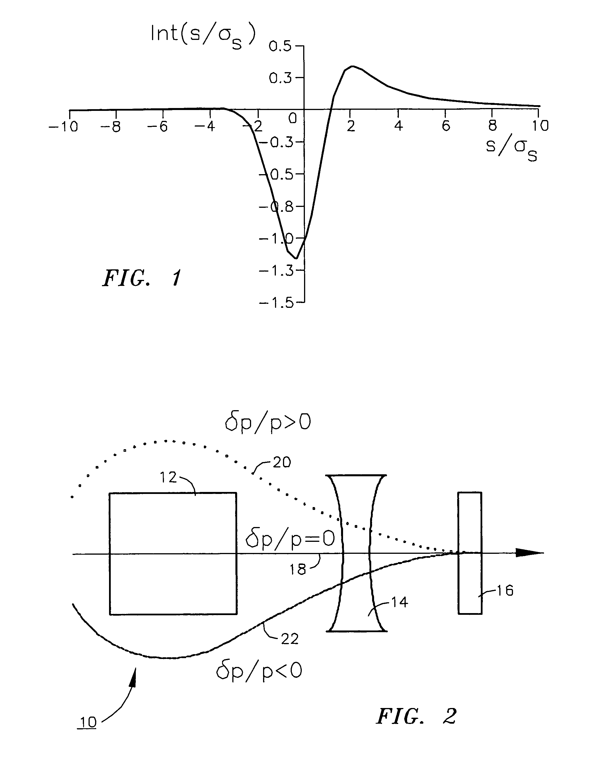
[0014]In this description, we assume a simple CSR model that has been detailed elsewhere (D. Douglas, “Suppression and Enhancement of CSR-Driven Emittance Degradation in the IR-FEL Driver”, JLAB-TN-98-012, 24 Mar. 1998). This description captures the fact that CSR causes a redistribution of energy in a bunch during bending, and as a consequence can significantly degrade emittance. In a bunch of length σz, charge / bunch Q, and energy E, an electron at position s will experience, while undergoing a bend of through angle Δθ at radius ρ, the following impulse in relative momentum δp / p given according to the wake function Int(s / σz) as shown in FIG. 1 and defined by the following formula.

[0015]δ⁢⁢pp={18000⁢⁢Q⁢⁢ρ1 / 3⁢Δθ31 / 3⁢2⁢⁢π⁢σs4 / 3⁢E}⁢Int⁡(sσs)

[0016]This interaction has two consequences:[0017]1) energy is redistributed across the bunch, lowering the energy of the tail and raising that of the head and shifting the centroid due to radiative loss; and[0018]2) when the electron is suddenly di...


PUM


Abstract

A method of avoiding CSR induced beam quality defects in free electron laser operation by a) controlling the rate of compression and b) using a novel means of integrating the compression with the remainder of the transport system: both are accomplished by means of dispersion modulation. A large dispersion is created in the penultimate dipole magnet of the compression region leading to rapid compression; this large dispersion is demagnified and dispersion suppression performed in a final small dipole. As a result, the bunch is short for only a small angular extent of the transport, and the resulting CSR excitation is small.

Description

[0001]The United States of America may have certain rights to this invention under Management and Operating Contract DE-ACO5-060R23177 from the United States Department of Energy.FIELD OF THE INVENTION[0002]The present invention relates to free electron laser beam quality and more particularly to methods of controlling coherent synchrotron radiation-driven degradation of beam quality during bunch length compression in the operation of such devices.BACKGROUND OF THE INVENTION[0003]Coherent synchrotron radiation (CSR) drives potentially severe degradation of beam quality when compressing a bunched electron beam. Prior art methods of bunching have been unable to avoid this problem, as all prior methods involve compressing the bunch slowly and / or traversing a large angle dipole with a short bunch. Degradation of beam quality due to these effects limits the performance of all existing designs for energy recovery linac (ERL) drivers of free electron lasers (FELs) at single bunch charges m...

Claims


Application Information

Patent Timeline
IPC IPC(8): H01J3/14
CPCH01S3/0903H01S3/102H05G2/00
Inventor DOUGLAS, DAVID R.TENNANT, CHRISTOPHER D.
Owner JEFFERSON SCI ASSOCS LLC
Learn More