Vehicle heat pump with a selective heat storing element and two circulation loops

a heat pump and selective technology, applied in the direction of indirect heat exchangers, domestic cooling devices, lighting and heating devices, etc., can solve the problems of increased fuel consumption of vehicles, and excessive drive of compressors, so as to enhance the thermal efficiency of the refrigeration cycle, enhance the thermal efficiency, and reliably liquefy the refrigerant

Inactive Publication Date: 2012-07-17
TOYOTA JIDOSHA KK
View PDF28 Cites 14 Cited by
  • Summary
  • Abstract
  • Description
  • Claims
  • Application Information

AI Technical Summary

Benefits of technology

[0012]If the temperature difference between the heat afferent medium and the first heat storage material is reduced, then the heat exchange efficiency between the two elements will decrease. According to the first aspect of the invention, however, by setting up heat exchange between the second heat storage medium and the heat afferent material as well, it is possible to accumulate the heat (or the cold energy) held by the heat afferent medium in the second heat storage medium. Accordingly, it is possible to transfer the heat contained by the heat afferent medium to the heat storage material to the necessary degree, thereby reducing the temperature of the heat afferent medium. On the other hand, if it is possible to receive heat sufficiently by the first heat storage material from the heat afferent medium and thereby to reduce the temperature of the heat afferent medium, then, since no heat exchange is set up between the second heat storage medium and the heat afferent medium, accordingly it becomes unnecessary to flow the second heat storage medium to a heat exchange side, so that it is possible to avoid unnecessary energy is consumed unnecessarily.
[0016]Accordingly, the thermal medium is provided to transport heat to the heat demand unit, and, if there is no demand for heat by the heat demand unit, then, if the heat afferent medium brings in heat, the thermal medium transports the heat held by the heat afferent medium to the first heat storage material, where the heat is stored. Accordingly, it is possible to promote heat storage by taking advantage of an existing thermal medium, and, due to this, it is possible to simplify the structure as a whole, while minimizing the number of additional components required.
[0018]Thus, it is possible to make the amount of the thermal medium, which functions as the second heat storage medium, large, accordingly, along with it being possible to make the amount of heat, which is stored by being received and being accumulated from the heat afferent medium, large. Also it is possible to supply an amount of heat corresponding to variations in the amount of heat requested by the heat demand unit, and moreover it is possible to suppress pulsation of the thermal medium.
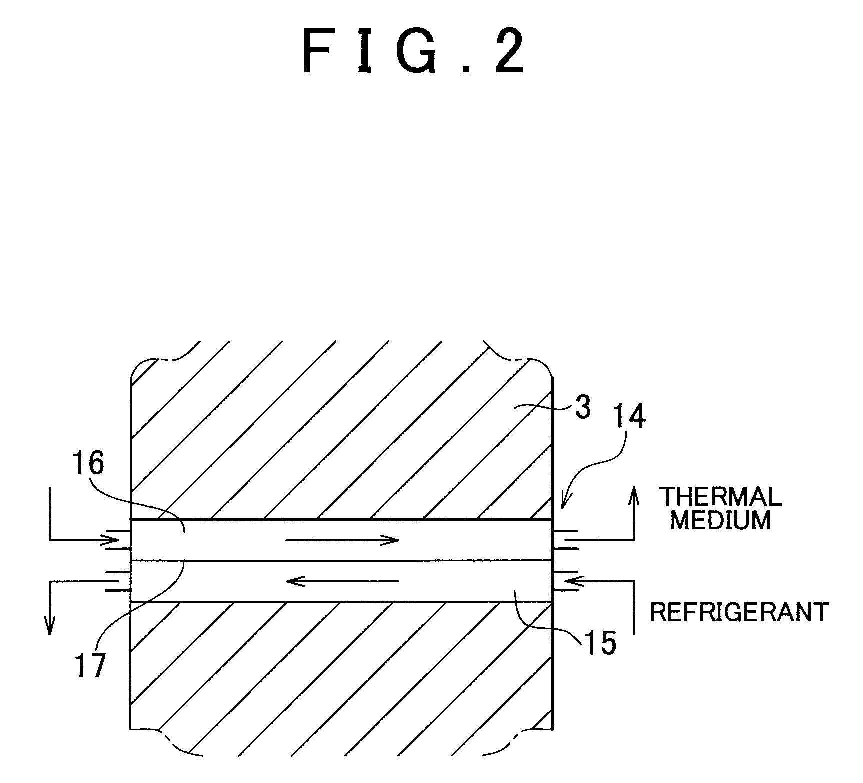
[0020]The division wall delimits the heat afferent medium and the first and second heat storage materials. The wall may be made thin, so long as the thickness is within the range that allows it to attain its objectives. As a result, it is possible to enhance the efficiency of heat exchange between all three of the heat afferent medium and the heat storage materials.
[0023]In the latter aspects of the invention, in the refrigeration cycle, it is possible sufficiently to extract and to store heat from the refrigerant. Accordingly, in addition to heat not being radiated uselessly, it is moreover possible to enhance the thermal efficiency of the refrigeration cycle, since it is possible reliably to liquefy the refrigerant. Furthermore, in the case of storage of cold, in addition to it being possible to perform such cold storage by sufficiently transferring heat to the refrigerant, also, by ensuring that the refrigerant is evaporated, it is possible to enhance the thermal efficiency as a whole.

Problems solved by technology

Conversely, if the vehicle runs at a comparatively high speed while coasting, it is possible that the compressor may be driven to an excessive degree.
Since, with the power being primarily outputted by the power source for driving the vehicle in this manner, from the point of view of the heat pump, the power supply is unstable, accordingly the loss of energy becomes great, and, by extension, there is a possibility that the fuel consumption of the vehicle will increase.
However, because the refrigerant, which is circulating in the refrigerant cycle, and the brine (the thermal medium), which is circulating to the heat exchanger within the passenger compartment, for air conditioning are both circulated according to demand, accordingly the time period of heat exchange in the heat storage type heat exchanger between the refrigerant and the brine (the thermal medium) or the heat storage material, and the heat exchange area and the like, impose a limitation, and there is a possibility that it may not necessarily be possible to perform heat storage or cold storage sufficiently.
Furthermore, since there is also a limitation upon the amount of heat that can be stored in the heat storage material, accordingly there is a possibility that it will not be possible sufficiently to recover the heat that could be recovered.

Method used


Image

  • Vehicle heat pump with a selective heat storing element and two circulation loops
  • Vehicle heat pump with a selective heat storing element and two circulation loops
  • Vehicle heat pump with a selective heat storing element and two circulation loops

Examples


Embodiment Construction

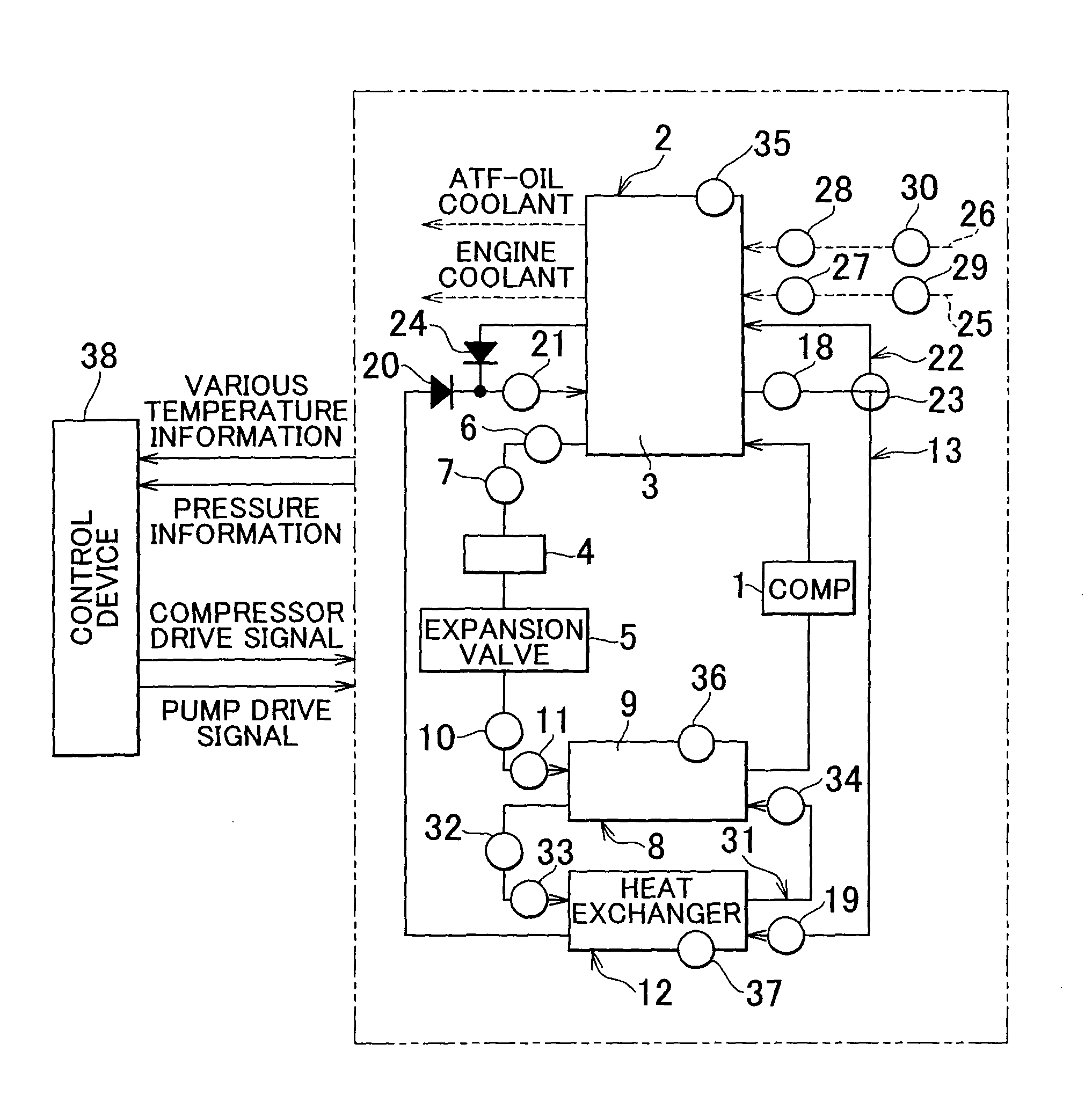
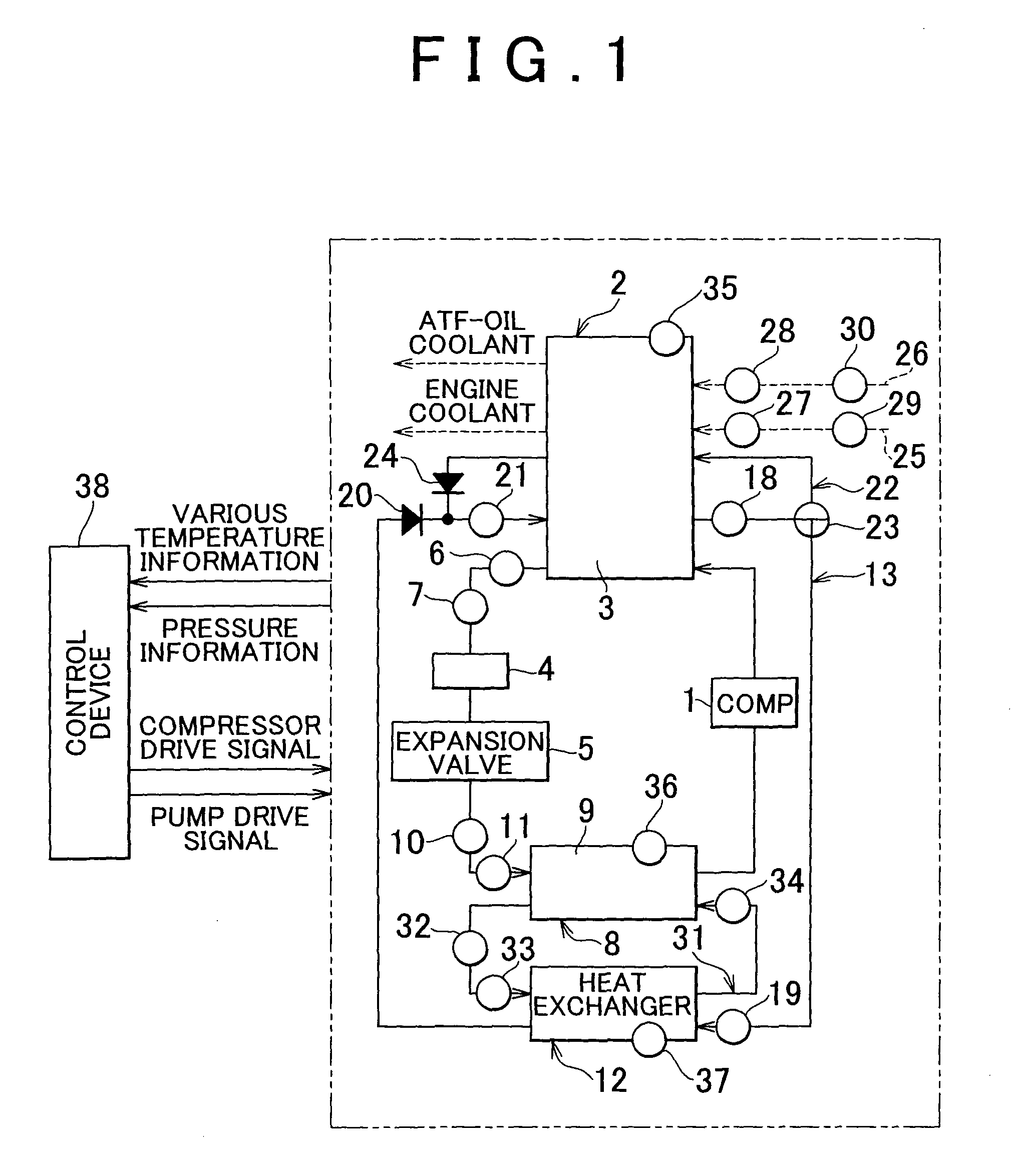
[0037]Next, this invention will be explained in concrete terms. The example shown in FIG. 1 is an example in which this invention has been applied to a condenser and an evaporator for a heat pump that operates on a refrigeration cycle, and, first to explain this refrigeration cycle: a compressor 1, which is driven by a power source such as an engine or an electric motor (neither of these is shown in the figures) or the like, compresses refrigerant, and is connected a heat storage device, such as the condensation device 2 (a condenser), on its discharge side. This heat storage type condensation device 2 liquefies the refrigerant by extracting, with a heat storage material 3, the heat from the refrigerant after its temperature has been elevated by pressurization and compression. The heat storage material 3 corresponds to the “first heat storage material” of the Claims. A sensible heat storage material or a latent heat storage material may be employed as the heat storage material 3, bu...


PUM


Abstract

A heat storage device that includes a first heat storage material and a second heat storage material, both of which accumulate heat by heat exchange with a heat afferent medium, and a changeover device that selectively either performs or intercepts heat storage by the second heat storage material. Accordingly, if the absorption of heat by the first heat storage material has decreased, the changeover device changes flow of the second heat storage material so that heat may be extracted from the heat afferent medium by the second heat storage medium. Thus, when the heat afferent medium is a refrigerant, it is possible to supercool the refrigerant thereof. Furthermore, since heat is extracted from the heat afferent medium and is accumulated, accordingly it is possible to anticipate effective utilization thereof.

Description

BACKGROUND OF THE INVENTION[0001]1. Field of the Invention[0002]The present invention relates to a heat storage device that temporarily accumulates heat (or cold energy) held in a medium such as a refrigerant or the like.[0003]2. Description of the Related Art[0004]In the art related to the invention, a compression type heat pump is known as one example of a heating device. The fundamental construction thereof is that a compressor compresses a refrigerant gas, the refrigerant gas dissipates heat so that it condenses, and then, the refrigerant is expanded adiabatically, and absorbs external heat so that it vaporizes, and thereafter is compressed again. Accordingly, if for example a vehicle is to be air conditioned, the air within the passenger compartment is cooled by taking advantage of the action of the refrigerant to absorb heat, so that the air in the passenger compartment is cooled.[0005]In a vehicle, the power source for propelling the vehicle, such as an engine or the like, is...

Claims


Application Information

Patent Timeline
Patent Type & Authority Patents(United States)
IPC IPC(8): F25B13/00F25D3/08F28F27/02F28D15/00F28D19/00F25B27/00F25D17/02F28D17/00
CPCB60H1/00492B60H1/00764B60H1/00885B60H2001/00928B60H2001/00949B60H1/32284
Inventor TSUBONE, KENJI
Owner TOYOTA JIDOSHA KK
Why Eureka
Try Eureka