Medical device coating by laser cladding

a technology of laser cladding and medical devices, applied in the direction of soldering media, magnetic materials, packaged goods types, etc., can solve the problems of reducing the accuracy of the dose delivered at the target site, unwanted webbing, and inaccuracy deposition of the therapeutic agen

Inactive Publication Date: 2012-07-17
BOSTON SCI SCIMED INC
View PDF1530 Cites 24 Cited by
  • Summary
  • Abstract
  • Description
  • Claims
  • Application Information

AI Technical Summary

Benefits of technology

[0006]The present invention is directed to improved medical device coating. The coating may be polymer-free, thereby eliminating any adverse effects of polymer coatings. In addition, or alternatively, the coating may be porous, facilitating the loading and release of therapeutic agent. The coating may be applied, if desired, on only the outer surface of the device, resulting in only abluminal delivery of therapeutic agent, which is desirable in certain applications.
[0008]When a stent is manufactured in accordance with an embodiment of the invention, the method employed may comprise providing a workpiece having inner and outer surfaces and positioning a nozzle adjacent the outer surface of the workpiece. A coating material may then be directed through the nozzle towards a surface of the workpiece. A laser beam may be directed at the coating material (and perhaps the workpiece) to form a melt pool on the surface of the workpiece. This melt pool of coating material (and perhaps material from the workpiece) can cool and harden, creating a porous layer of the coating material secured to the surface of the workpiece. Portions of the workpiece, which may be in the shape of a tube, may be cut away to form a coated stent structure. This coated stent structure may then be loaded with therapeutic agent.
[0009]In some embodiments, the porous coatings may be selectively applied in specified areas along the length of the workpiece or stent material, and a number of porous coatings may be applied. The coating may be applied such that it controls or otherwise sustains the elution rate of therapeutic agent carried by the coating.

Problems solved by technology

Dipping and spraying systems can provide for inaccurate deposition of the therapeutic agent.
This “webbing” is unwanted, as it may reduce the accuracy of the dose delivered at the target site.
Also, when polymers are used in these spraying and dipping processes, their use can inhibit the effectiveness of the therapeutic agent as both the polymer and the therapeutic agent may be easily deployed from the device rather than the therapeutic agent alone.
Moreover, the polymer may create an inflammatory reaction.

Method used


Image

  • Medical device coating by laser cladding
  • Medical device coating by laser cladding
  • Medical device coating by laser cladding

Examples


Embodiment Construction

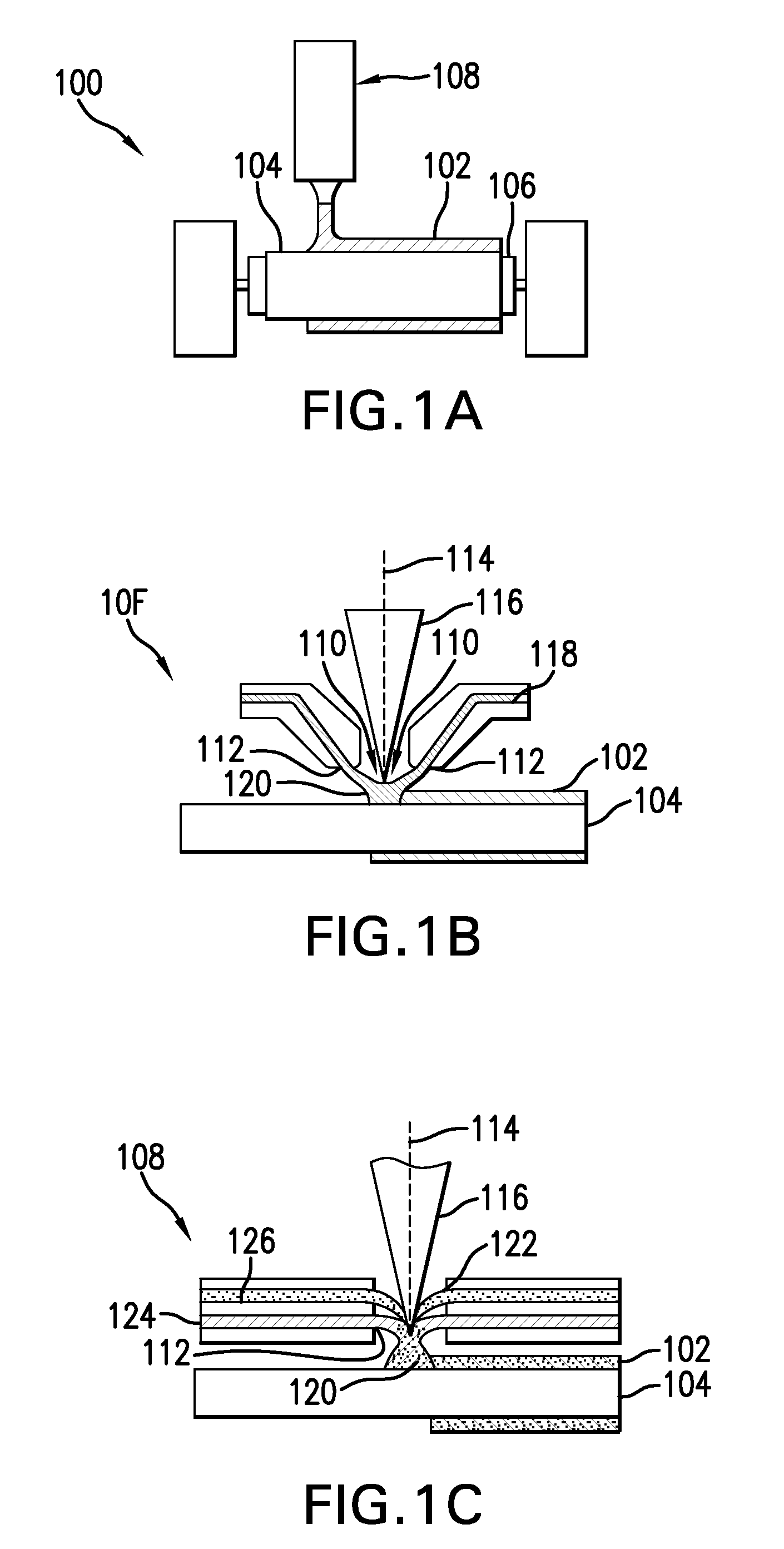
[0023]Conventional laser cladding processes have been used for hard-facing (e.g., applying a layer of harder material (e.g., tungsten carbide) onto a softer base layer of material (e.g., stainless steel)). These conventional processes contemplate the use of one or more homogenous hard-faced layer(s), where pores and cracks in the hard-faced layer are undesirable. Laser cladding processes have been utilized for hard-facing new components during production and restoring worn-down surfaces of existing components.

[0024]For example, as discussed in M. F. Schneider, “Laser Cladding” (Ph. D. Thesis, University of Twente, Enschede, The Netherlands, 1998), pages 1-181, laser cladding processes have been used in industrial applications to hard-face and refurbish gas turbine blades and diesel engine exhaust valves. In addition, as discussed in U.S. Pat. No. 6,122,564 to Koch, which issued on Sep. 19, 2000, laser cladding has also been proposed for use in general industrial processes for improv...


PUM

PropertyMeasurementUnit
wavelengthsaaaaaaaaaa
wavelengthaaaaaaaaaa

Abstract

Methods for making medical devices having porous coatings. Methods may comprise providing a tubing section having inner and outer surfaces and positioning a nozzle proximate to a target surface of the parent tubing section. A powder form of the porous coating may be delivered toward the tubing section, and a laser may be directed at the powder to melt the powder to form a melt pool. The melt pool can solidify to form the porous coating on the target surface. Portions of the parent tubing section may then be cut away to form the support structure of the medical device, such as a stent.

Description

CROSS REFERENCE TO RELATED APPLICATION[0001]The present application claims priority to U.S. provisional application Ser. No. 60 / 953,000 filed Jul. 31, 2007, the disclosure of which is incorporated herein by reference in its entirety.TECHNICAL FIELD[0002]The present invention generally relates to coated medical devices and methods and systems of making them.BACKGROUND[0003]The positioning and deployment of implantable medical devices at a target site is an often-repeated procedure of contemporary medicine. The devices, which can include implantable stents, cardiac rhythm management leads, neuromodulation devices, implants, grafts, defibrillators, filters, catheters and / or any implantable devices for systemic release of drugs, may be deployed for short and sustained periods of time, and may be used for many medicinal purposes, including the delivery of therapeutic agent and the reinforcement of recently re-enlarged lumens. When therapeutic agent is delivered by these devices it may be...

Claims


Application Information

Patent Timeline
Patent Type & Authority Patents(United States)
IPC IPC(8): A61L33/00B05D3/00B05D1/36B05D1/02B22D3/00B29D22/00
CPCA61L27/16A61L27/56A61L31/146A61L31/16B23K26/34B23K26/3206B23K26/3246B23K26/3273B23K35/0244B23K35/365A61L27/54Y10T428/1355A61L2300/608B05D1/12B05D3/0466B05D3/06B05D7/52B05D2202/00B23K2201/34Y10T428/12Y10T428/1352B23K26/32B23K26/324B33Y80/00B23K2101/34B23K2103/30B23K2103/50B23K2103/52
Inventor FLANAGAN, AIDENO'CONNOR, TIM
Owner BOSTON SCI SCIMED INC
Why Eureka
Try Eureka