
Metal-free vertically-aligned nitrogen-doped carbon nanotube catalyst for fuel cell cathodes

a carbon nanotube, vertical alignment technology, applied in the direction of cell components, electrochemical generators, non-conductive materials with dispersed conductive materials, etc., can solve the problems of high cost, high cost, and inability to use noble metal catalysts such as platinum in large-scale commercial applications,

Active Publication Date: 2012-07-17
UNIV OF DAYTON
View PDF14 Cites 15 Cited by
  • Summary
  • Abstract
  • Description
  • Claims
  • Application Information

AI Technical Summary

Benefits of technology

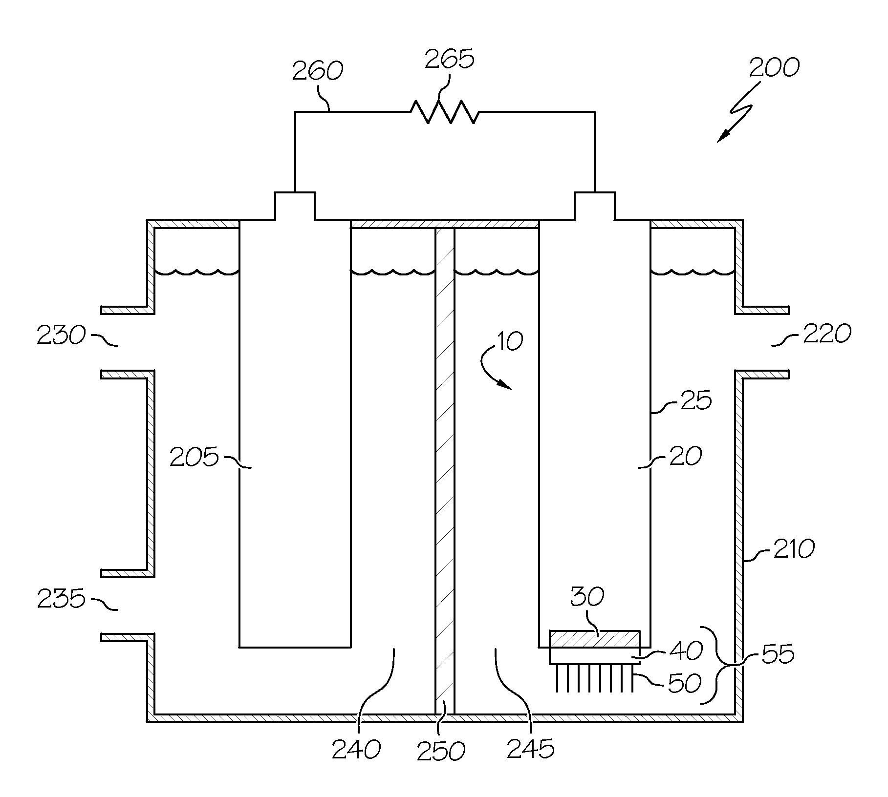
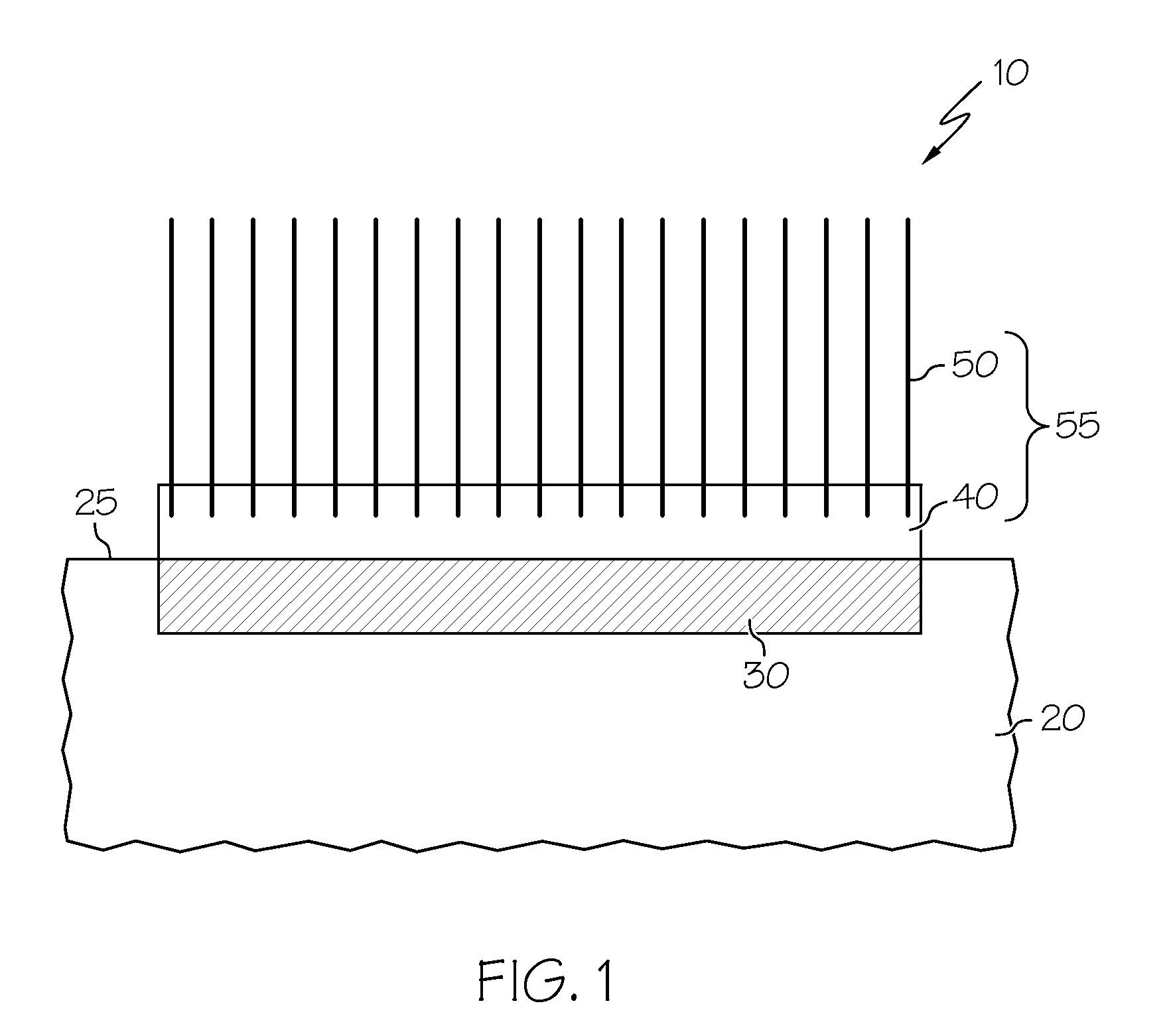
[0015]These needs are met by the embodiments disclosed herein. According to the present disclosure, arrays of vertically-aligned nitrogen-doped carbon nanotubes (VA-NCNTs) are provided as metal-free catalytic layers for fuel cell cathodes. These metal-free catalytic layers provide for increased catalytic activity, increased long-term stability, and increased tolerance to crossover effects than oxygen-reduction cathodes comprising metals such as platinum.
[0019]Accordingly, it is a feature of the embodiments of the present disclosure to provide fuel cell cathodes comprising metal-free, efficient ORR catalysts, methods for fabricating the fuel cell cathodes, and low-cost, high-performance fuel cells comprising the cathodes. Other features of the embodiments of the present disclosure will be apparent in light of the description of the disclosure embodied herein.

Problems solved by technology

But in general, the use of high-cost noble metal catalysts such as platinum has precluded large-scale commercial applications.
In addition to the high costs involved, platinum electrodes in commercial fuel cells may be further limited by issues such as susceptibility of platinum electrodes to time-dependent drift and to deactivation by catalyst poisons such as carbon monoxide (CO).

Method used


Image

  • Metal-free vertically-aligned nitrogen-doped carbon nanotube catalyst for fuel cell cathodes
  • Metal-free vertically-aligned nitrogen-doped carbon nanotube catalyst for fuel cell cathodes
  • Metal-free vertically-aligned nitrogen-doped carbon nanotube catalyst for fuel cell cathodes

Examples


Embodiment Construction

[0027]In the following detailed description, reference is made to the accompanying drawings that form a part of this application, and in which are shown by way of illustration, and not by way of limitation, specific embodiments in which the disclosure may be practiced. It is to be understood that other embodiments may be utilized and that logical, mechanical, and electrical changes may be made without departing from the spirit and scope of the present disclosure.

[0028]Among various non-noble-metal catalysts for the oxygen-reduction reaction (ORR), carbon nanotubes formed by high-temperature treatment of ferrocene, for example, have been demonstrated to show promising catalytic activity. This activity has been theorized to be attributed to active sites of FeN2—C and / or FeN4—C within the nanotubes. At such active sites, iron (Fe) may be coordinated with two or four nitrogen (N) atoms arranged in a pyridinic or a pyrrolic structure.

[0029]On the other hand, carbon nanotubes produced by ...


PUM

PropertyMeasurementUnit
lengthsaaaaaaaaaa
lengthsaaaaaaaaaa
diametersaaaaaaaaaa

Abstract

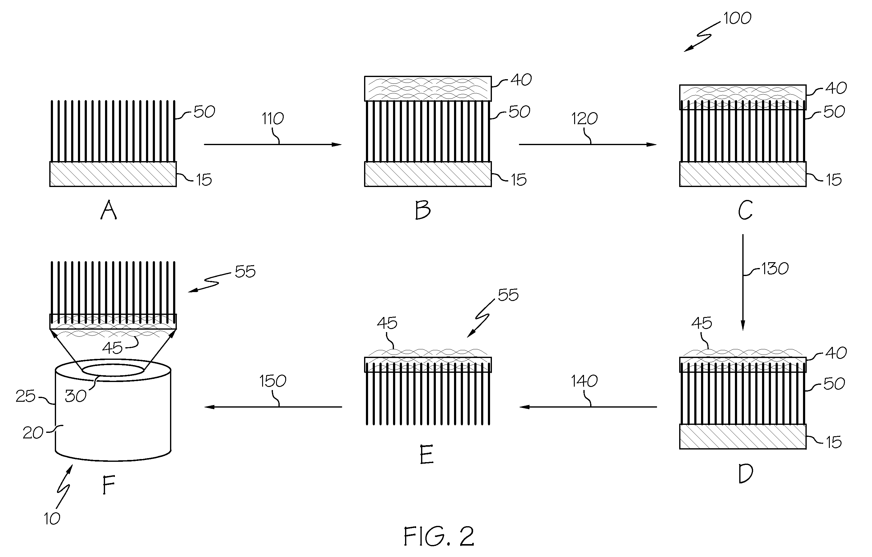
Metal-free fuel cell cathodes having a catalytic layer of vertically-aligned, nitrogen-doped carbon nanotubes (VA-NCNTs) are provided. The fuel cell cathodes comprise a cathode body, a binder layer attached to an outer surface of the cathode body, and the catalytic layer, which is supported by the binder layer. The binder layer may comprise a composite of a conductive polymer and doped or undoped nonaligned carbon nanotubes. In a method for forming the fuel cell cathodes, the VA-NCNTs may be formed by pyrolysis of a metalorganic compound and integration of the nanotubes with nitrogen. The binder layer is applied, and the resulting supported nanotube array may be attached to the cathode body. Fuel cells comprising the fuel cell cathodes are provided. The fuel cell cathodes comprising VA-NCNTs demonstrate superior oxygen-reduction reaction performance, including for electrocatalytic activity, operational stability, tolerance to crossover effects, and resistance to CO poisoning.

Description

CROSS-REFERENCE TO RELATED APPLICATIONS[0001]This application claims the benefit of priority under 35 U.S.C. §119(e) of U.S. Provisional Application Ser. No. 61 / 138,982, filed Dec. 19, 2008.TECHNICAL FIELD[0002]The present disclosure generally relates to fuel cells and, more particularly, to metal-free carbon nanotubes for use as cathode electrodes in fuel cells.BACKGROUND[0003]A fuel cell is based on an electrochemical cell, wherein two electrodes are in electrical contact with one or more electrolytes that can be solids or liquids. An electrically insulating, ion-permeable membrane may also be situated within the electrolyte. Because the membrane is electrically insulating, electrons formed at the anode are forced to travel through an external circuit back to the cathode to maintain the cathode reaction. Between the anode and the cathode, the electrons can be used to supply power to devices connected to the external circuit or can be fed into an energy storage system such as a bat...

Claims


Application Information

Patent Timeline
Patent Type & Authority Patents(United States)
IPC IPC(8): H01M4/90H01M8/00
CPCH01B1/24H01M4/8605H01M4/8668H01M4/96H01M8/1002Y02E60/523H01M8/1007Y02E60/50
Inventor DAI, LIMING
Owner UNIV OF DAYTON
Learn More