
Brake system

a brake system and brake fluid technology, applied in the direction of brake cylinders, process and machine control, instruments, etc., can solve the problems of inability to operate the electric motor, etc., and achieve the effect of preventing the sudden decrease in the brake fluid pressure of the wheel cylinder

Inactive Publication Date: 2012-07-24
HONDA MOTOR CO LTD
View PDF27 Cites 25 Cited by
  • Summary
  • Abstract
  • Description
  • Claims
  • Application Information

AI Technical Summary

Benefits of technology

Prevents sudden brake fluid pressure drops by maintaining pressure until the master cylinder can take over, ensuring consistent braking performance and comfortable pedal feel even when the slave cylinder fails.

Problems solved by technology

If a problem occurs that renders the electric motor inoperative when an electric brake force generator (slave cylinder) of the BBW brake system is generating brake fluid pressure to operate a wheel cylinder, a failsafe or failure backup process for braking is performed by supplying brake fluid pressure generated by a master cylinder to the wheel cylinder via the slave cylinder.
However, at the moment when the slave cylinder becomes unable to generate a driving force for pushing a piston, the piston is pushed back by brake fluid pressure within the wheel cylinder.
Therefore, there is a problem that the brake fluid pressure within the wheel cylinder suddenly decreases until the brake fluid pressure supplied from the master cylinder is built up.

Method used


Image

  • Brake system
  • Brake system
  • Brake system

Examples


Embodiment Construction

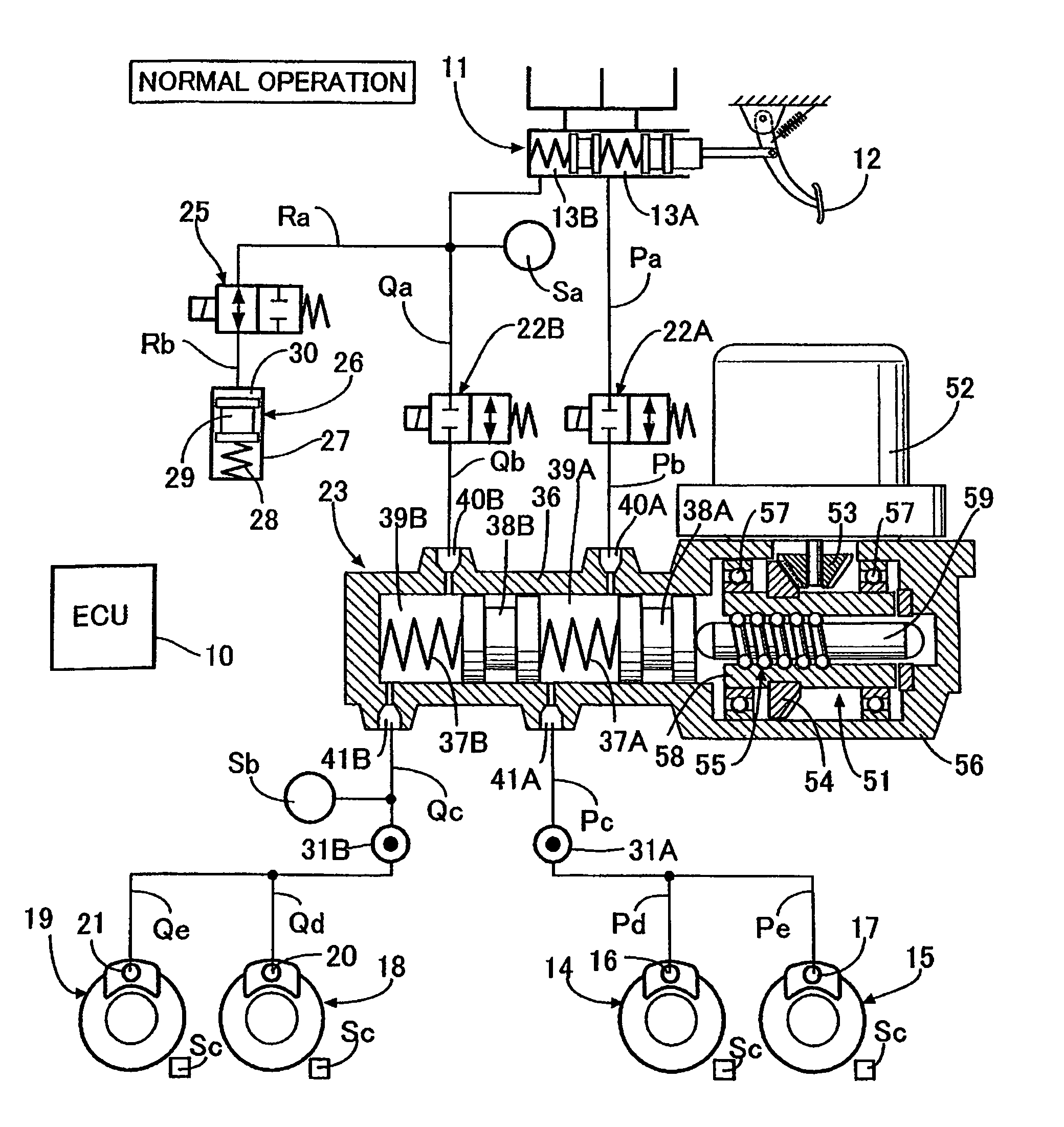
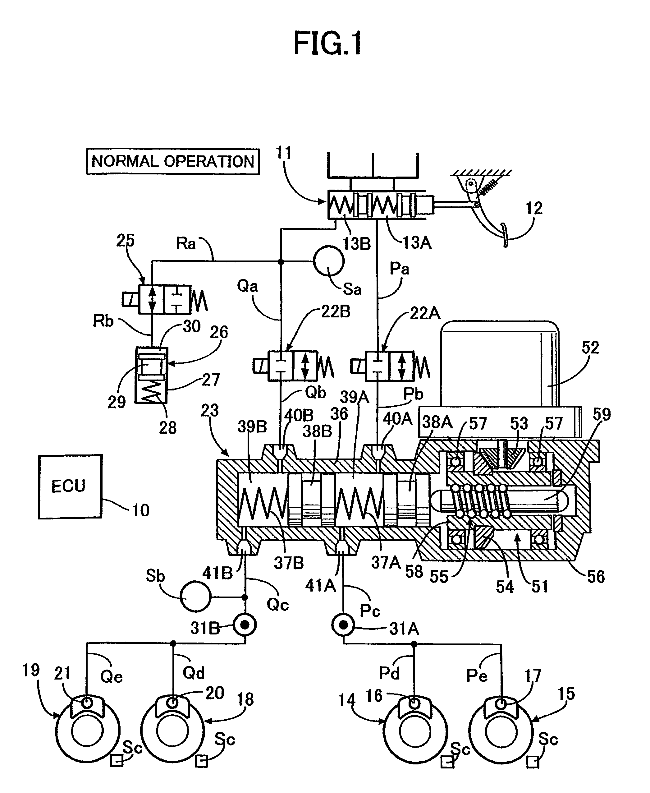
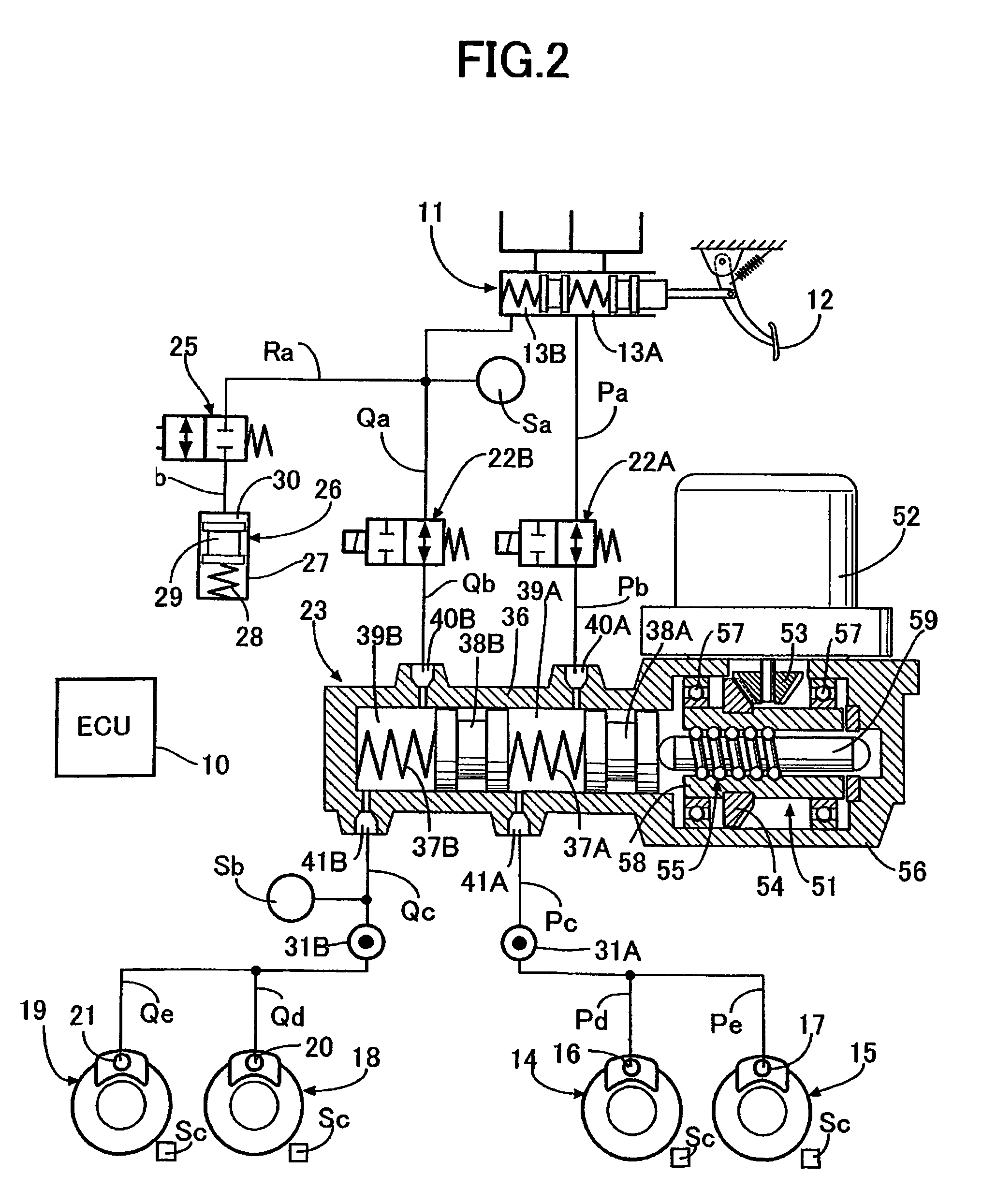
[0028]A first exemplary embodiment of the present invention will be described with reference to FIGS. 1 to 4B.

[0029]As shown in FIG. 1, a tandem master cylinder 11 has two first fluid pressure chambers 13A and 13B which output brake fluid pressure according to a pushing force applied to a brake pedal 12 by a driver depressing the brake pedal 12. One of the first fluid pressure chamber 13A is connected to wheel cylinders 16 and 17 of disc brake devices 14 and 15 for braking, for example, a left front wheel and a right rear wheel, through fluid passages Pa, Pb, Pc, Pd, and Pe. The first fluid pressure chamber 13B is connected to wheel cylinders 20 and 21 of disc brake devices 18 and 19 for braking, for example, a right front wheel and a left rear wheel, through fluid passages Qa, Qb, Qc, Qd, and Qe.

[0030]A shutoff valve 22A, which is a normally open solenoid valve, is provided between the fluid passages Pa and Pb. A shutoff valve 22B, which is a normally open solenoid valve, is provid...


PUM


Abstract

A brake system includes a master cylinder which generates brake fluid pressure by a braking operation of a driver, an electric motor-driven slave cylinder which generates brake fluid pressure based on an electric signal responsive to a braking operation of a driver, and a wheel cylinder for braking a wheel by the brake fluid generated in the master cylinder or slave cylinder. During normal operation of the brake system, the brake fluid generated in the slave cylinder is transferred to the wheel cylinder. During abnormal operation of the brake system, the brake fluid generated in the master cylinder is transferred to the wheel cylinder. The brake system also includes an opening and closing valve in a fluid passage connecting the slave cylinder to the wheel cylinder. When a problem occurs with the slave cylinder, the opening and closing valve is closed for a predetermined amount of time.

Description

CROSS-REFERENCE TO RELATED APPLICATIONS[0001]The present invention claims priority under 35 USC §119 based on Japanese patent application No. 2007-62315 filed 12 Mar. 2007. The subject matter of this priority document is incorporated by reference herein.BACKGROUND OF THE INVENTION[0002]1. Field of the Invention[0003]The present invention relates to a brake system comprising a master cylinder that generates brake fluid pressure by a braking operation of a driver, and a slave cylinder that generates brake fluid pressure by a driving force of an electric motor that operates according to an electrical signal which is responsive to the braking operation by the driver.[0004]2. Description of the Related Art[0005]Japanese Patent Application Laid-open No. 2005-343366 discloses a brake system of the type referred to as a brake by wire (BBW) brake system, which converts a braking operation of a driver into an electrical signal used to operate an electric brake force generator or generating me...

Claims


Application Information

Patent Timeline
Patent Type & Authority Patents(United States)
IPC IPC(8): B60T8/88B60T8/17B60T8/48B60T17/08B60T17/18
CPCB60T8/4081
Inventor HATANO, KUNIMICHI
Owner HONDA MOTOR CO LTD
Learn More