Bone bridge providing dynamic compression on bone fractures

a dynamic compression and bone fracture technology, applied in the field of orthopedic bone plates and bone staples, can solve the problems of limited ability to apply controlled amounts of compressive force to fractures, static bone plates do not provide or maintain such conditions, and affect the healing process of fractured bones

Active Publication Date: 2012-07-24
KINAMED
View PDF7 Cites 14 Cited by
  • Summary
  • Abstract
  • Description
  • Claims
  • Application Information

AI Technical Summary

Problems solved by technology

However, most conventional compression plates and staples are made of metal materials having moduli of elasticity much higher than that of bone and therefore a limited ability to apply controlled amounts of compressive force to a fracture.
In particular, use of such bone plates produces a mechanical system in which the majority of the stress is borne by the plate rather than the bone, a situation sometime referred to as “stress-shielding.” This situation is deleterious even to healthy, uncompromised bone, and can seriously impair the healing process in a fractured bone.
Conventional, static bone plates do not provide or maintain such conditions.
Such methods can introduce initial compression, but the compression is difficult to maintain.
Small movements of the bone can interact with the typically high-modulus metallic plate or staple, causing large fluctuations of the compressive load.
Furthermore, some resorption may occur as a prelude to osteosynthetic growth, resulting in contraction of the bone in the region of the fracture and releasing the compressive force.
Even small contractions will produce slack sufficient to leave the fracture without compression (because the high-modulus metal plate cannot accommodate the contraction).
Such materials appear promising, but offer their own challenges.
There are still unanswered questions concerning the biocompatibility, strength, stability, reliability, wear, and ease of manufacture and handling.

Method used


Image

  • Bone bridge providing dynamic compression on bone fractures
  • Bone bridge providing dynamic compression on bone fractures
  • Bone bridge providing dynamic compression on bone fractures

Examples


first embodiment

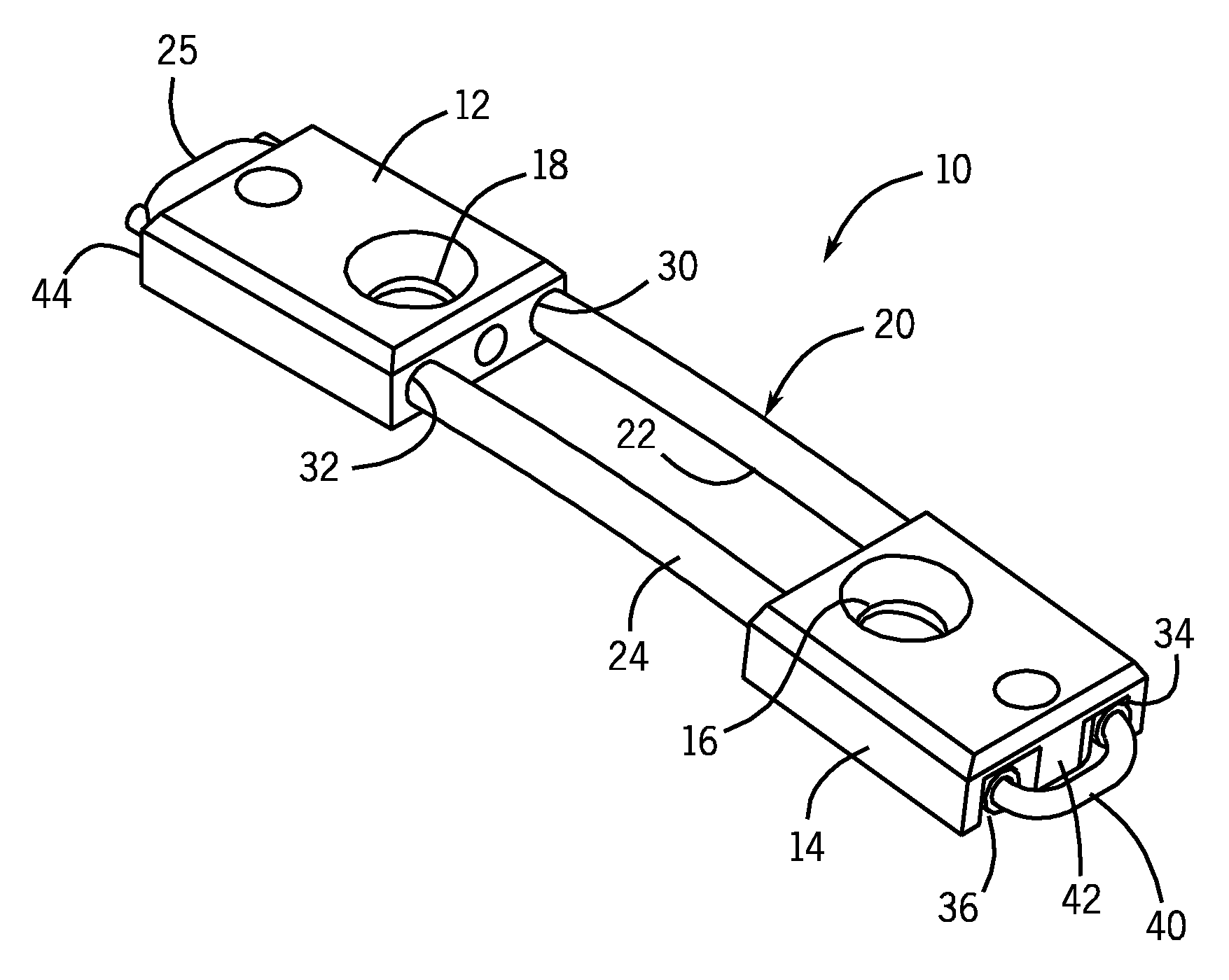
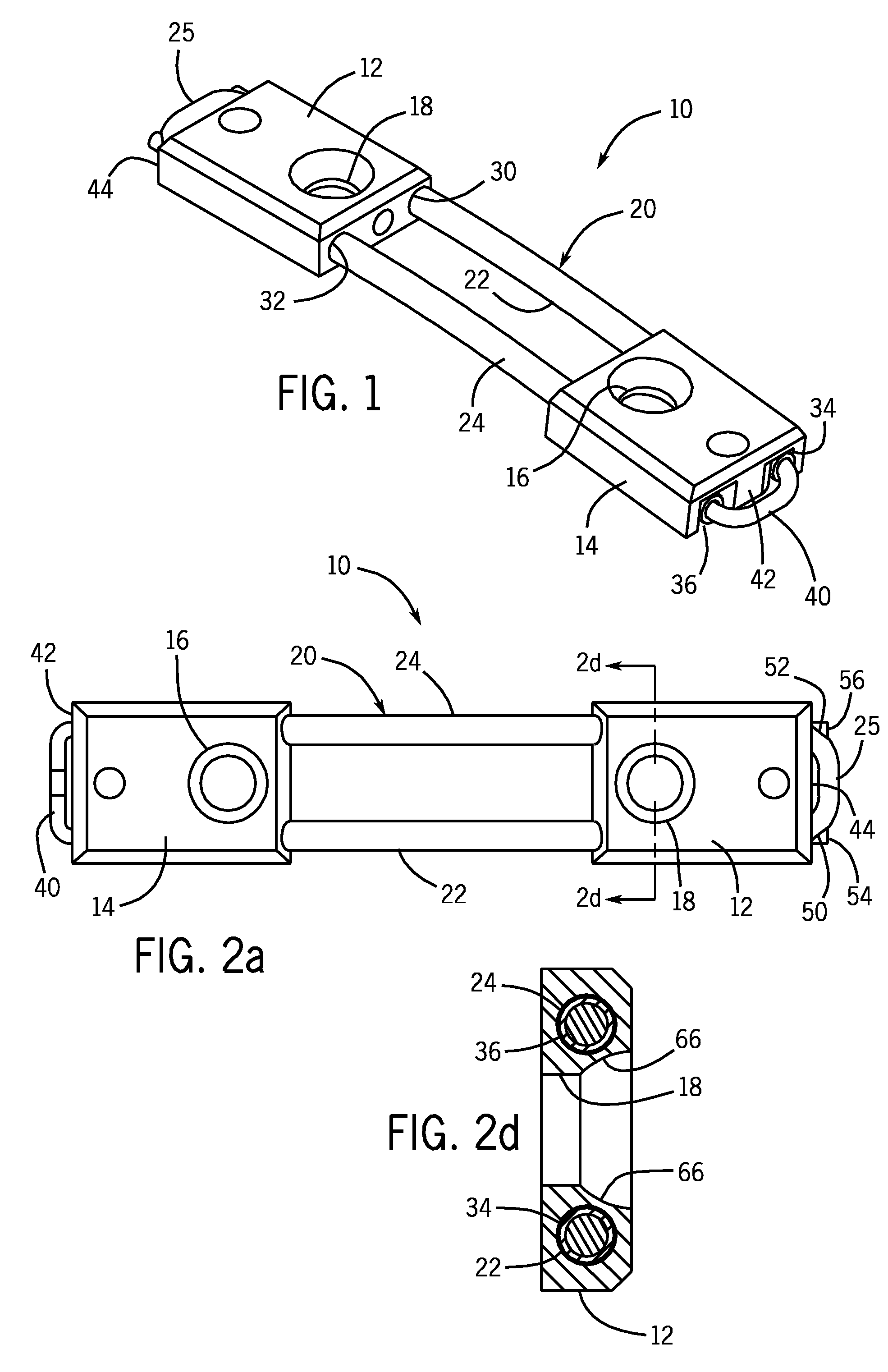
[0023]FIG. 1 shows generally a particular first embodiment of a bone plate system or bone bridge 10 in accordance with the invention. The bone bridge 10 is shown in a relaxed state as further explained below. The bone bridge 10 includes a first fixed bone fragment plate 12 and a second movable bone fragment plate 14 each of which has a countersunk hole or aperture 16 and 18 through which bone screws or other fasteners may extend to individually fix the plates 12 and 14 to different bone fragments on different sides of a bone fracture. A hollow U-shaped cylindrical tube 20 has a 180 degree reverse bend 25 at its proximal end and defines two parallel spaced-apart legs 22 and 24 open at their distal ends. The plates 12 and 14 and the U-shaped tube 20 are preferably fabricated from stainless steel or titanium. The legs 22 and 24 extend through the plates 12 and 14 in cylindrical channels or passages 30 and 32 in plate 12 and cylindrical channels or passages 34 and 36 in plate 14. The pa...

second embodiment

[0040]FIG. 7 shows generally a particular second embodiment of a bone plate system or bone bridge 100 in accordance with the invention in a relaxed state. The embodiment includes a first fixed bone plate 102 and second movable bone plate 104 each of which has one or more countersunk holes or apertures 106 and 108 through which bone screws or other fasteners may extend to individually fix the plates 102 and 104 to different bone fragments on different sides of a bone fracture. A hollow U-shaped cylindrical tube 110 has a 180 degree reverse bend 115 at its proximal end and defines two parallel spaced-apart legs 112 and 114 open at their distal ends. The plates 102 and 104 and the U-shaped tube 110 are preferably fabricated from stainless steel. The legs 112 and 114 extend through the plates 102 and 104 in cylindrical channels or passages 120 and 122 in plate 102 and cylindrical passages 124 and 126 in plate 104. The passages 120, 122, 124 and 126 are of a slightly larger inside diamet...


PUM


Abstract

An orthopedic bone bridge, suitable for internally fixating and stabilizing fractured bones. The bone bridge includes: first and second bone plates for attachment to bone fragments by bone screws or the like on opposite sides of a bone fracture, a pair elongate parallel hollow legs on which the plates are mounted and the second plate is slidably engaged and is moveable with respect to the first plate, and an elastic cable or microcable attached to the first plate and extending down through the legs and around said second plate. The elastic cable is configured to provide a controlled tensile force between the plates when they are pulled into a longitudinally spaced apart position with the bone bridge then applying a correspondingly compressive force onto the bone fracture when the plates are secured to bone fragments on opposite sides of a bone fracture.

Description

CROSS REFERENCE TO RELATED APPLICATIONS[0001]This application claims the benefit of U.S. patent application Ser. No. 11 / 454,344 filed on Jun. 16, 2006, which is incorporated herein by reference.BACKGROUND OF THE INVENTION[0002]1. Field of the Invention[0003]This invention relates generally to medical and surgical devices and methods and more specifically to orthopedic bone plates and bone staples suitable for internally fixating and stabilizing fractured bones.[0004]2. Description of the Related Art[0005]Many bony fractures require stabilization that cannot be provided by external splints or casts; internal fixation is therefore required. Bone plates and bone staples are among the most common artificial orthopedic implants, and are commonly used to stabilize and internally fixate bony fractures.[0006]A conventional bone plate is essentially a rigid metal plate drilled with guide holes through which bone screws can be passed. Bone screws are usually inserted through the mounting hole...

Claims


Application Information

Patent Timeline
Patent Type & Authority Patents(United States)
IPC IPC(8): A61B17/66
CPCA61B17/8004A61B17/842
Inventor REIMELS, WILLIAM J.HACK, BRADFORD H.
Owner KINAMED
Why Eureka
Try Eureka