Method of converting pyrolyzable organic materials to biocarbon
a technology of organic materials and biocarbons, applied in the direction of lighting and heating apparatus, drying machines, liquid hydrocarbon mixture production, etc., can solve the problems of large charcoal production quantities at relatively low conversion efficiency of raw materials, high cost of providing a pressurized reactor controlling a non-steady state process, and the mode of operation and high cost of providing a pressurized reactor. , to achieve the effect of controlling the recovery of heavier tars
- Summary
- Abstract
- Description
- Claims
- Application Information
AI Technical Summary
Benefits of technology
Problems solved by technology
Method used
Image
Examples
example 1
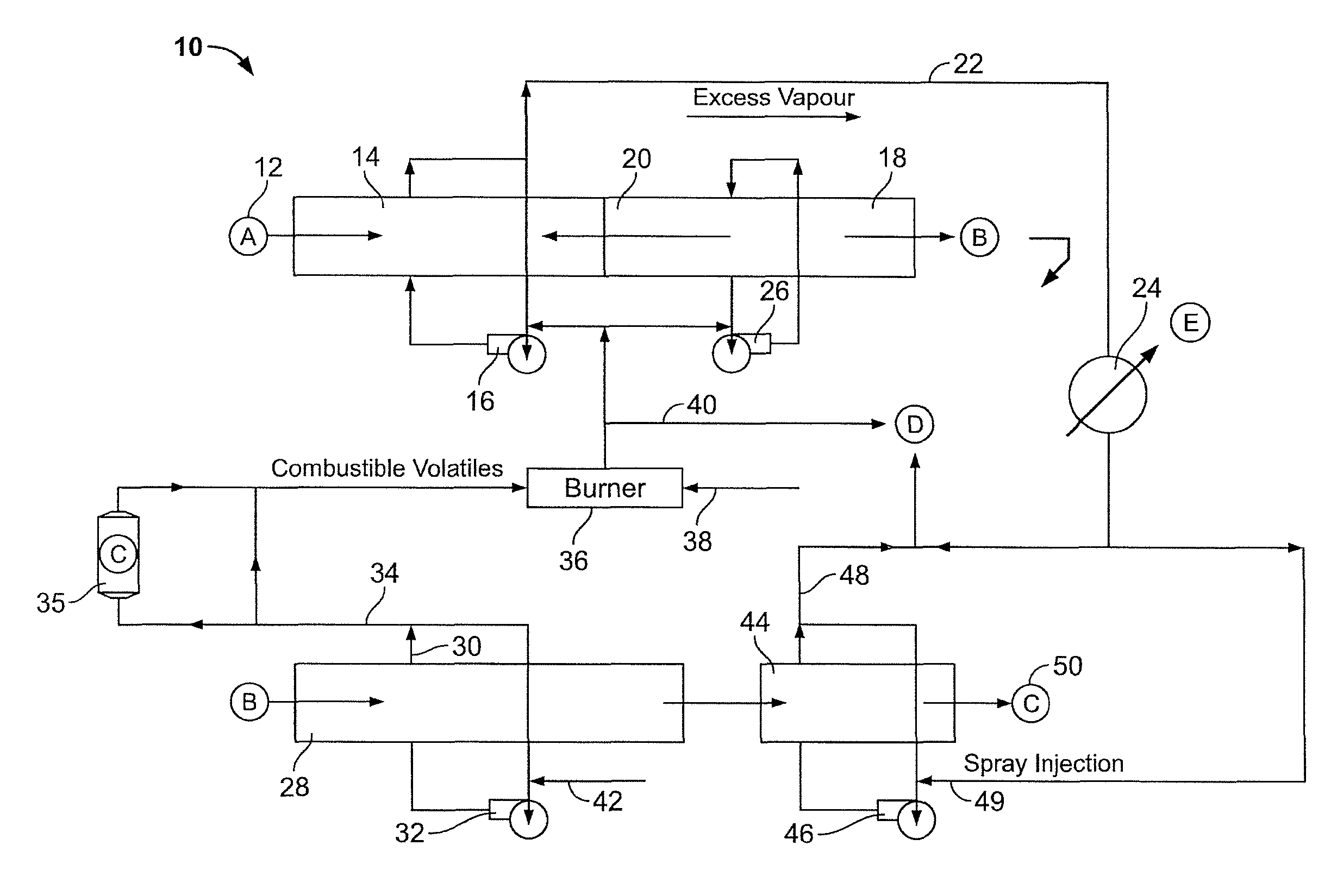
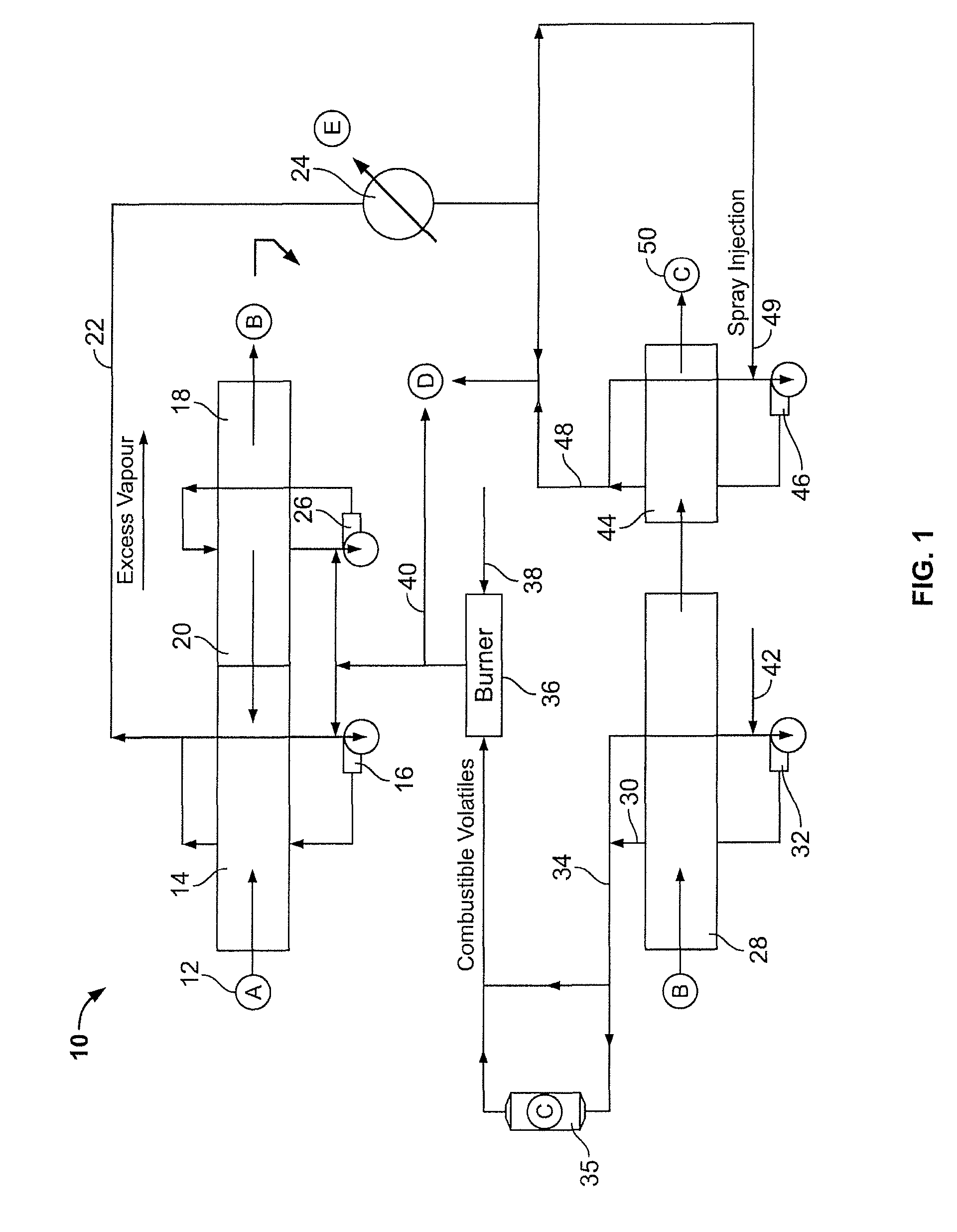
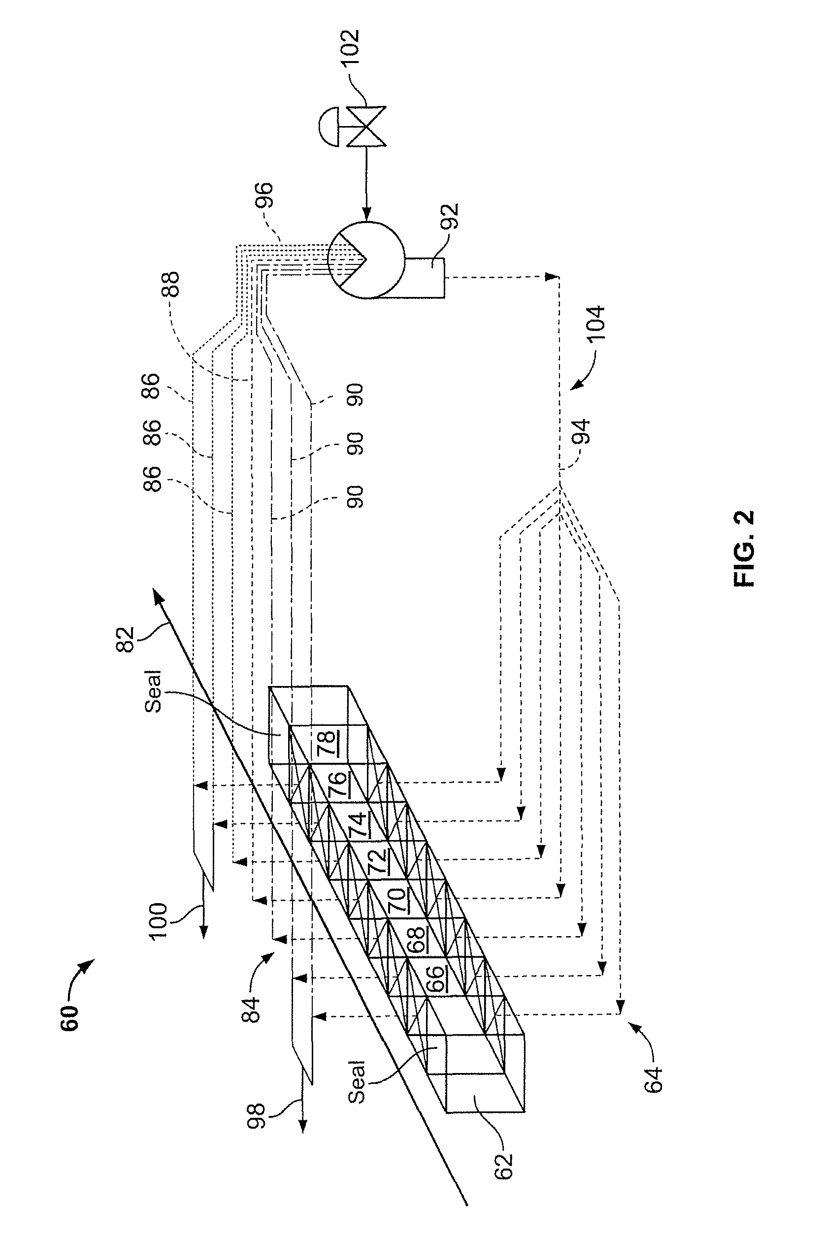
[0046]A carbonizer circuit, consisting of a drying stage, pyrolyzing stage and cooling stage, was constructed with the features described in FIG. 1 and FIG. 2. The individual bins were carbon steel boxes 40 centimeters on edge with open tops, screen bottoms and solid walls; each bin contained a nominal 65 liters of entering pyrolyzable organic material. The vapors within the carbonizer were extracted from a common plenum above all bins with a single extraction point from the common plenum above bin position 76 on FIG. 2 and returned to a common plenum under all bins with the specific return points to the common plenum being under bin position 74 and 78 on FIG. 2.
[0047]The carbonizer main fan was a large squirrel cage fan, with nominally 45-degree outward forcing fan blades. The rotating squirrel cage was 60 centimeter ID, 70 centimeter OD and 20 centimeters high. The main fan rotated at 450 rpm when driven at 60 hertz by the variable frequency drive (VFD) of the main fan. The other ...
example 2
[0049]SPF wood chips were processed by the carbonizer circuit of Example 1 with the higher temperature vapors setpoint of 350 C, as controlled by the addition of metered air prior to the carbonizer main fan. The carbonizer main fan was operated at frequencies of 30 hertz, 50 hertz and 70 hertz on the variable frequency drive (VFD) of the main fan. The push rate was typically 15 minutes, although 20 minute push intervals were used on occasion at 30 hertz to facilitate necessary heat transfer to the entering bins.
[0050]The pyrolyzing stage demonstrated improving heat exchange between the bins with increasing fan speed, as evidenced by an accelerated heating of cooler entering bins and decreased temperature gradient within the higher temperature bins. Furthermore, the yield of biocarbon product per unit of entering dry biomass increased with increasing fan speed, as measured by weighing dried coupons of wood blocks before and after carbonization. The calculated yields on a weight basis...
example 3
[0052]SPF wood chips were processed by the carbonizer circuit of Example 1 at higher temperature vapors setpoints over the range of 350 C to 425 C, as controlled by the addition of metered air prior to the carbonizer main fan. The carbonizer main fan was operated at a fixed frequency of 70 hertz on the variable frequency drive (VFD) of the main fan. The push rate was varied between runs at 15-minute push intervals and runs at 20-minute push intervals and the effect on adsorption capacity and volatile matter measured.
[0053]Independent of the higher temperature vapors setpoint over the range of 350 C to 425 C, the adsorption capacity was at least 40 percent higher in the biocarbon products produced at 20-minute push intervals as compared to the biocarbon products produced at 15-minute push intervals. In addition, the 15-minute push interval biocarbon product evidenced approximately 10 percent higher volatile matter content than the 20-minute push interval biocarbon product.
PUM
| Property | Measurement | Unit |
|---|---|---|
| temperatures | aaaaa | aaaaa |
| temperatures | aaaaa | aaaaa |
| temperatures | aaaaa | aaaaa |
Abstract
Description
Claims
Application Information
 - R&D
- Intellectual Property
- Life Sciences
- Materials
- Tech Scout
- Unparalleled Data Quality
- Higher Quality Content
- 60% Fewer Hallucinations
Browse by: Latest US Patents, China's latest patents, Technical Efficacy Thesaurus, Application Domain, Technology Topic, Popular Technical Reports.
© 2025 PatSnap. All rights reserved.Legal|Privacy policy|Modern Slavery Act Transparency Statement|Sitemap|About US| Contact US: help@patsnap.com


