High speed flywheel containment

a flywheel and containment technology, applied in the field of flywheels, can solve the problems of increasing friction and wear, increasing the speed of the flywheel within the vehicle, so as to achieve the effect of reducing friction and wear, and extending the time for the flywheel to break up

Active Publication Date: 2012-08-07
PUNCH FLYBRID LTD
View PDF23 Cites 5 Cited by
  • Summary
  • Abstract
  • Description
  • Claims
  • Application Information

AI Technical Summary

Benefits of technology

[0011]An advantage of the present invention is that on failure of the flywheel, the time taken for the flywheel to break up is extended, and the energy is released over a longer period of time. It is therefore easier to safely contain the debris produced, and may allow sufficient time for a control system to safely reduce the speed of the failed flywheel.
[0012]Preferably the annular ring is provided on a flange provided on the housing, such that the surface which contacts the annular ring is located on an inside surface of the periphery. An advantage of this is that when the hub contacts the ring on oscillation of the flywheel, the surface speed, and therefore the energy generated by the frictional contact, is much lower than it would be if contact were made on the outside of the rim.
[0013]The annular rings may be provided with inwardly and / or outwardly projecting flanges, whereby the flanges have an abutment face in close proximity to the periphery end faces, the webs, or some other substantially radial surface. An advantage of providing flanges on the annular rings having abutment faces is that on failure of the flywheel, the flywheel is caused to contact an increased surface area, therefore causing a greater amount of friction thereby causing a greater reduction in speed of the flywheel. Furthermore, if the failure of the flywheel progresses to the state where the rim and the shaft are disconnected or the stiffness of the connection has sufficiently deteriorated, the axial movement of the flywheel rim is controlled, and the period during which the rim rotates substantially in its original position around the original centreline of the shaft is extended, thereby further dissipating energy.
[0014]A surface coating may be applied to the annular ring and / or the part of the hub which contacts the ring on oscillation of the flywheel. The surface coating could be selected, for example, to control the rate of deceleration or the heat generation. A coating with a high coefficient of friction such as a brake lining material would provide a high rate of deceleration, which may be appropriate in some applications. In other applications a coating with a low coefficient of friction such as Diamond Like Carbon (DLC) would reduce the rate of deceleration and minimise heat generation.
[0015]Preferably the design of the hub is such that the highest stress is in the webs that connect the shaft to the rim, causing the primary failure mode of the flywheel to be failure of the metal hub by cracking. Particular design features which would ensure that the primary failure mode is cracking of the metal hub could include, for example, particular mass distributions at different radii. The stress occurring in the webs on rotation of the flywheel is also affected by the thickness of the web. For example, a web of substantially constant thickness would result in the highest stress occurring towards the centre of the flywheel, due to the effect of the mass of the portion further away from the centre effectively pulling on the portion at the centre as the flywheel rotates.
[0016]An advantage of the primary failure mode of the flywheel being cracking of the hub is that as the hub fails by cracking and breaks up, the composite rim, which has a considerable reserve of strength, acts to contain the resultant debris.

Problems solved by technology

However, flywheels used in vehicles typically run at speeds of around 20,000 revs per minute or lower, due to certain constraints.
Firstly, the speed at which a flywheel within a vehicle can operate is limited by susceptibility to vibration caused on operation of the vehicle, which can cause significant strain on the flywheel mounting and bearings, thereby increasing friction and wear and reducing the efficiency of the flywheel, and furthermore constituting a potential safety risk.
On failure of the flywheel, cracking of the hub occurs at a crack site, causing a loss of stiffness of the connection between the flywheel and the bearings.
As a result, the flywheel becomes unstable, causing it to oscillate on the shaft.
If the oscillation is unrestrained, it will grow larger, thus generating excessive strain at the crack site and causing the crack to lengthen until complete failure of the flywheel occurs, i.e. the rim becomes disconnected from the bearings.
When the flywheel fails, the large amount of kinetic energy stored in the flywheel dissipates very quickly and a large instantaneous pressure is generated within the flywheel housing.
It is necessary to contain the debris generated by the failure, which can require a large and heavy containment means.
The problems encountered on failure of a flywheel and containment of the debris are extenuated by the short amount of time during which the energy is dissipated.

Method used


Image

  • High speed flywheel containment
  • High speed flywheel containment
  • High speed flywheel containment

Examples


Embodiment Construction

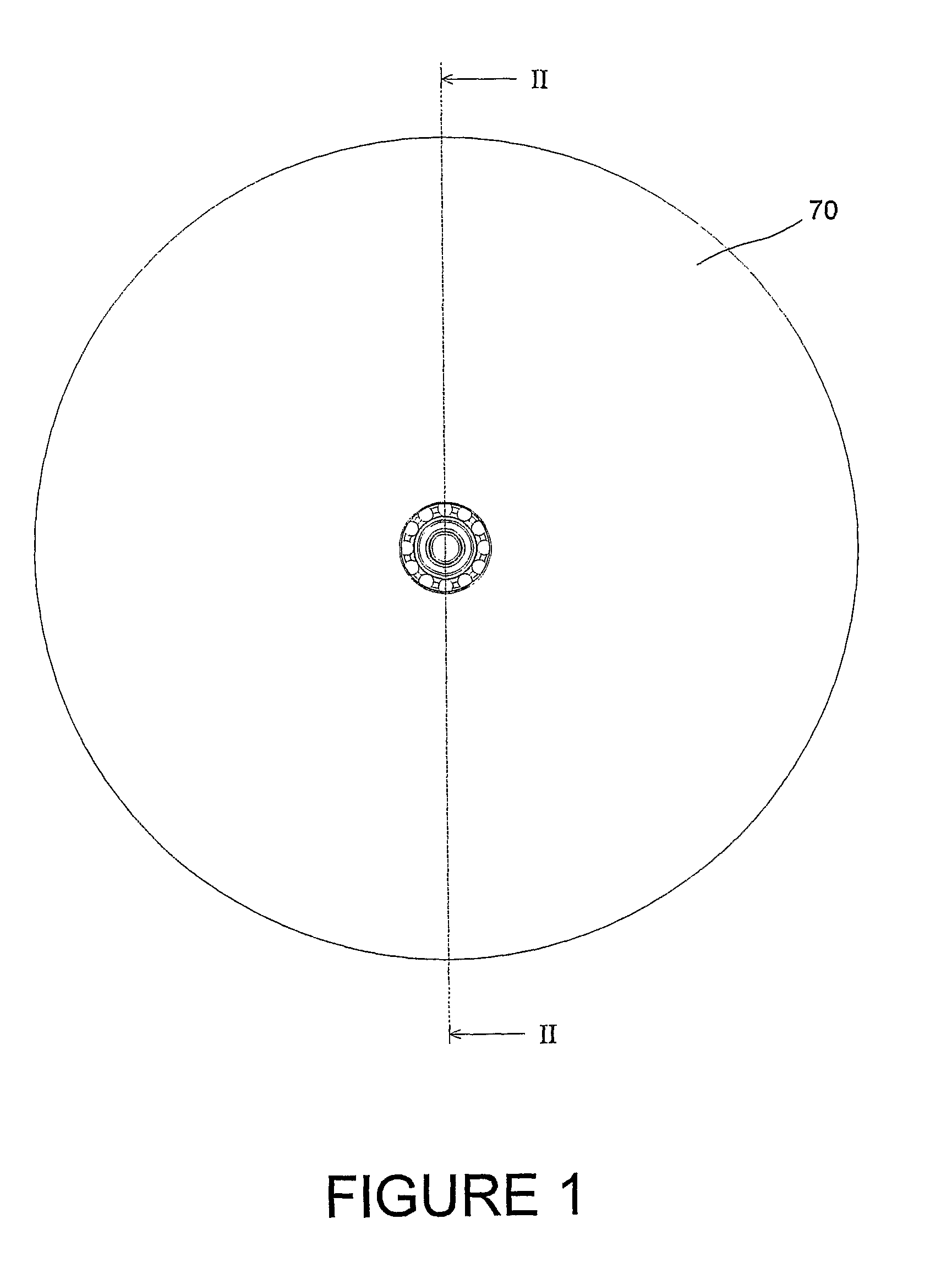
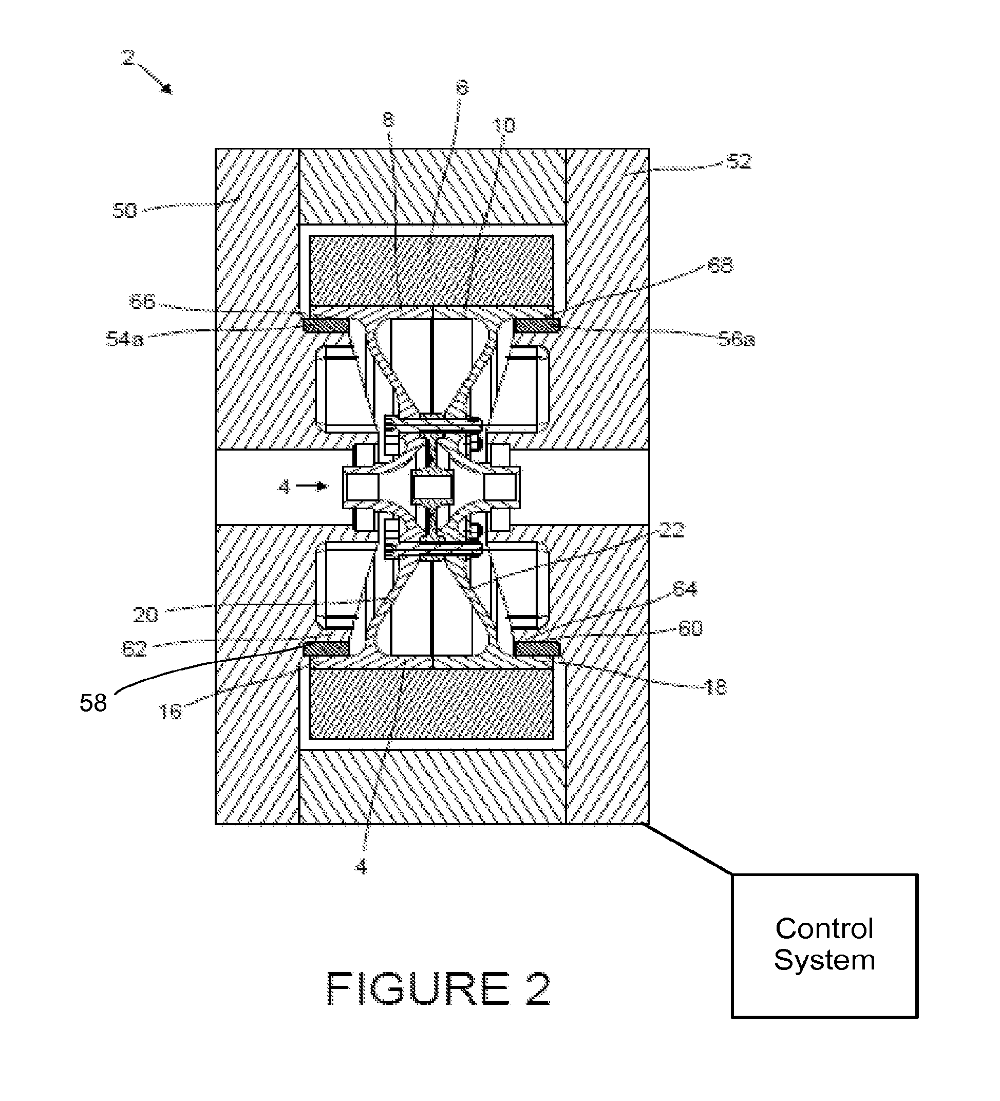
[0021]Referring to FIGS. 1 and 2, the flywheel 2 comprises steel hub arrangement 4 with a wound carbon fibre composite rim 6.

[0022]The hub 4 is formed of two halves 8, 10, each having a periphery 16, 18. The two halves 8, 10 of the hub are of equal diameter and the inner diameter of the rim 6 is selected such that when it is fitted over the outside of the hub arrangement 4, a radial interference fit is achieved, thus ensuring that the rim 6 stays in compression with the hub 4 at high operating speeds.

[0023]The hub is formed with webs 20, 22, which extend from the inside surface of the periphery towards the centre of the flywheel. The stress generated in the web by rotation of the flywheel is higher than that in the radial thickness of the rim, such that the primary failure mode of the flywheel will be the failure of the hub by cracking of the web.

[0024]The flywheel 2 is contained in a housing 70 comprising two end caps 50, 52 and a vacuum is maintained within the housing.

[0025]Annul...


PUM


Abstract

The present invention provides a high inertia flywheel for a vehicle including a hub, a periphery of which is surrounded by a rim, and a housing, wherein at least one annular ring is provided on either side of the flywheel, whereby, on oscillation of the flywheel, a contact surface of the flywheel contacts against a contact surface of the annular ring, thus causing friction.

Description

CROSS-REFERENCE TO RELATED APPLICATIONS[0001]This application is the U.S. National Phase under 35 U.S.C. §371 of International Application No. PCT / GB2008 / 001133, filed Mar. 28, 2008, designating the United States and published in English on Nov. 27, 2008, as WO 2008 / 142363, which claims priority to United Kingdom Application No. 0709456.8, filed May 17, 2007.FIELD OF THE INVENTION[0002]This invention relates to flywheels, and particularly to high speed flywheels for use in vehicles.[0003]DESCRIPTION OF RELATED ART[0004]Flywheels typically comprise a relatively heavy mass, arranged to rotate around a shaft. Bearings are provided to rotatably couple the shaft to a housing. The use of flywheels in vehicles is known, for example as an aid for acceleration or deceleration of the vehicle. It is also known to use a flywheel as a battery, whereby the kinetic energy of the flywheel is converted into electrical energy. The kinetic energy of a flywheel is directly proportional to the rotationa...

Claims


Application Information

Patent Timeline
Patent Type & Authority Patents(United States)
IPC IPC(8): H02K7/02
CPCF16F15/315Y10T74/2119Y10T74/2132B60K6/00F16C39/00
Inventor HILTON, JONATHAN JAMES ROBERTCROSS, DOUGLAS ISAAC LASCELLES
Owner PUNCH FLYBRID LTD
Why Eureka
Try Eureka