Optical image-capturing apparatus

an image-capturing apparatus and optical technology, applied in the field of optical image-capturing apparatus, can solve the problems of disadvantageous restrictions in optical resolution characteristics, inconvenient configuration for imaging at low light intensity, and significant constraints on the optical design with respect to the arrangement of components, etc., to achieve simple electrical control, high resolution, and high resolution.

Inactive Publication Date: 2012-08-07
KOWA CO LTD
View PDF10 Cites 5 Cited by
  • Summary
  • Abstract
  • Description
  • Claims
  • Application Information

AI Technical Summary

Benefits of technology

[0065]In the configuration of the present invention, two-dimensional image-capturing means has been employed as the detector, and low-speed scanning means and low-speed re-scanning means are used which operate at the frame rate of the image-capturing means. Therefore, the scanning confocal optical system can be simplified, and the electrical controls are also simple.
[0066]Since the projected light beam and the received light beam are coaxial in the optical system as the apparatus dedicated for SLMs or SLOs, two-dimensional reflection images (or fluorescent images) with high resolution, sensitivity, contrast, and gradation properties can be obtained at high speeds corresponding to the frame rate of the image-capturing element.
[0067]If necessary, a measurement function using an OCT interferometer system can be added. This allows multifunctionality, such as the ability to obtain tomographic image information in the depth direction while obtaining a two-dimensional reflection image (or fluorescent image) of the object.
[0068]If a two-dimensional image-capturing element is modified to be more precise, more sensitive, or faster in the future, SLMs and SLOs functions can be improved by simply upgrading the apparatus. In other words, a very practical and economical optical image-capturing apparatus can be realized.

Problems solved by technology

However, since three sides of a multifaceted mirror are used as the scanning means, there are significant constraints on the optical design with respect to the arrangement of components.
Also, since the pupil of the objective lens is split for light projection and light detection, the optical resolution characteristics are disadvantageously restricted.
However, since a one-dimensional line sensor is used as the detector, the choice of detectors is very limited, and since there are few high-sensitivity detectors, the configuration is not suitable for imaging at low light intensity.
However, since the reflective surface of the oscillating mirror and the pupil plane of the objective lens are divided in two for light projection and light detection, there are big design constraints, and optical resolution characteristics disadvantageously undergo restriction.

Method used


Image

  • Optical image-capturing apparatus
  • Optical image-capturing apparatus
  • Optical image-capturing apparatus

Examples


embodiment 1

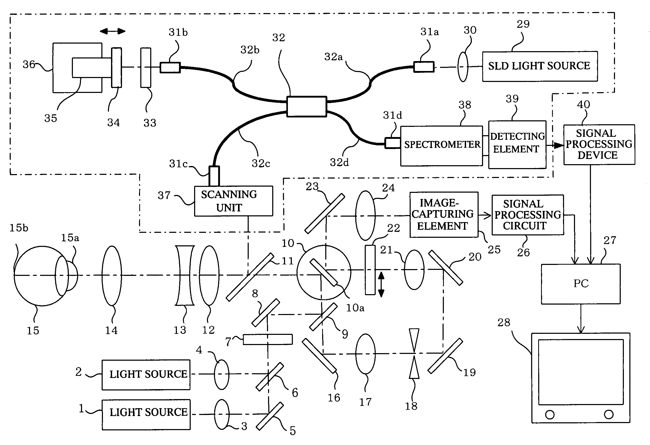
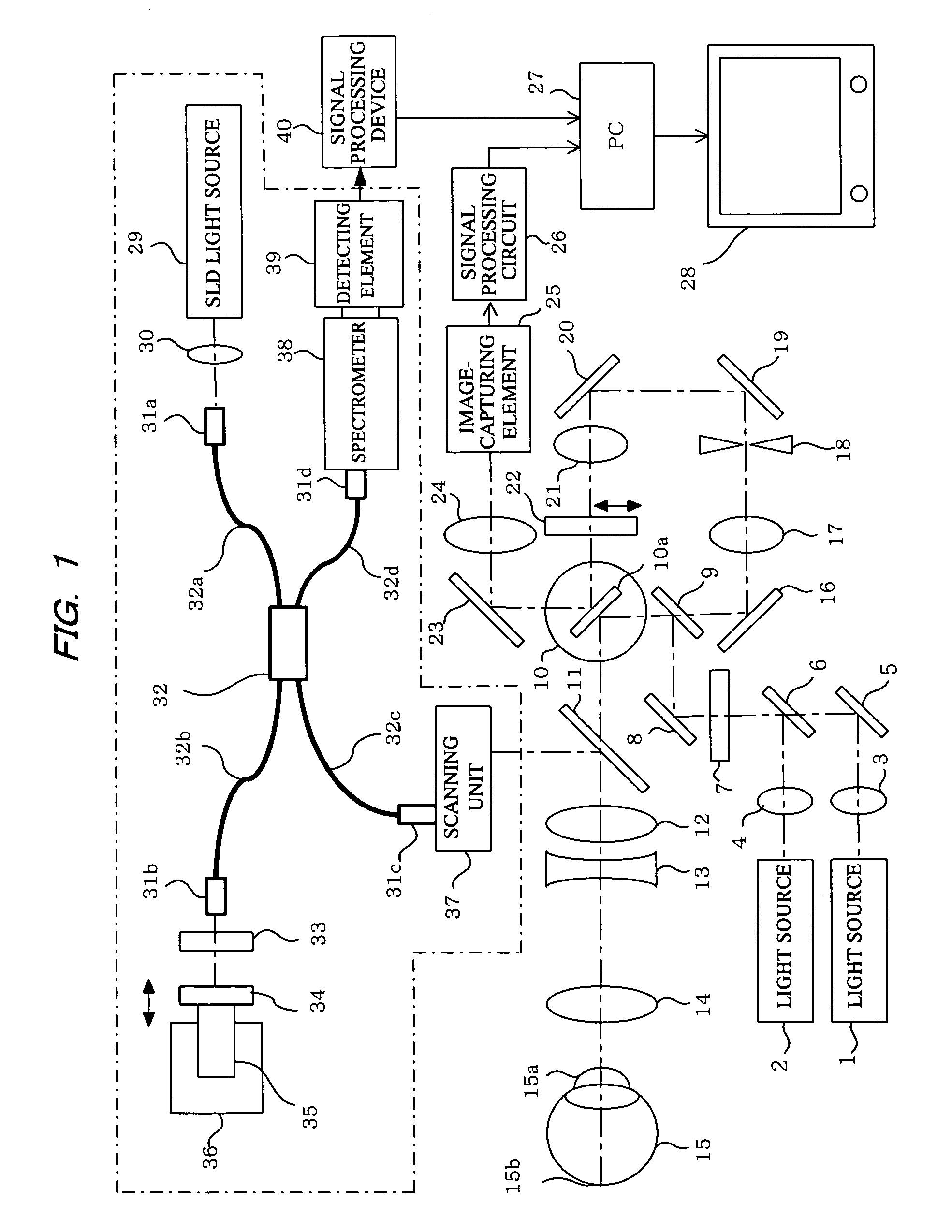
[0076]In FIG. 1, reference numerals 1 and 2 denote light sources (first light source) used to observe a reflection image or a fluorescent image of an object to be observed. These are predetermined light sources with high luminance such as a light-emitting diode that generates high-luminance light beams (a super luminescent diode or SLD), a semiconductor laser (laser diode), or a solid-state laser. The wavelength is, for example, within a range from approximately 490 nm to 800 nm. Light sources 1 and 2 can be used selectively if necessary in order to use different light beams with different wavelengths as required. The light beams from the light sources 1, 2 are collimated by lenses 3, 4, and combined on the same optical axis via a mirror 5 and a dichroic mirror 6.

[0077]The light beam via the mirror 5 and the dichroic mirror 6 is transformed into a flat line beam (a light beam focused linearly on the focal plane) via a cylindrical lens 7, is reflected by a mirror 8, and is made incid...

embodiment 2

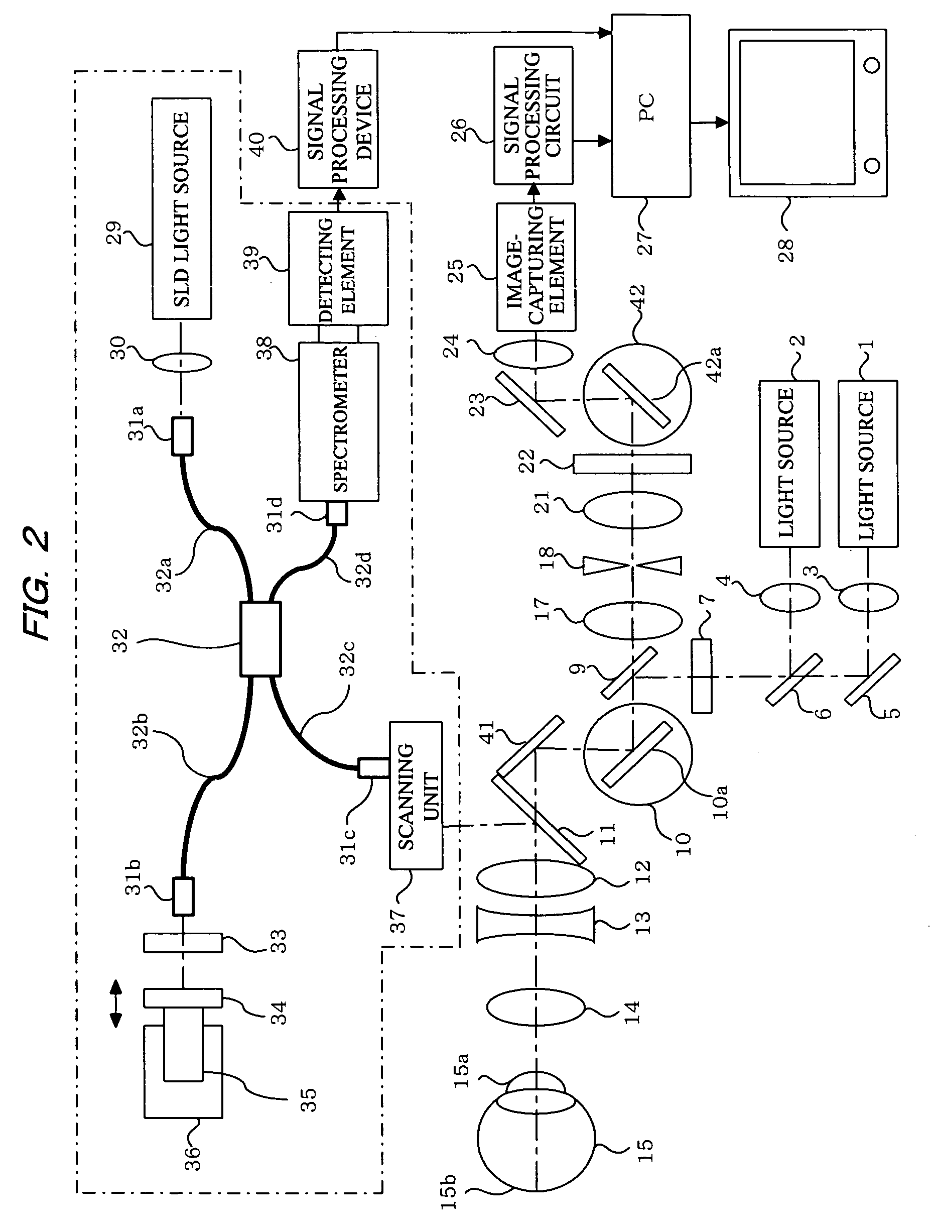
[0101]FIG. 2 shows a system configuration of the embodiment of the present invention that differs from the embodiment in FIG. 1. In FIG. 2, the object to be observed is also assumed to be a human eyeball (anterior ocular segment or ocular fundus). In FIG. 2, the elements identical to the structural elements in FIG. 1 are denoted by the same reference numerals. The structural elements denoted by the same reference numerals in FIG. 2 have the same configuration and function as those in FIG. 1. The following is primarily a description of the points of difference with FIG. 1.

[0102]Light beams from the light sources (SLD or LD) 1, 2 for observing a reflection image or fluorescent image pass through the dichroic mirror 6 and the like, and are shaped by the cylindrical lens 7 into a line beam (slit-shaped beam) which is linear at the focal position. The light beam shaped into a slit is reflected by the beam splitter 9 (BS, optical path splitting member), and then scanned one-dimensionally ...


PUM


Abstract

Light beams from light sources 1, 2 are scanned by a galvano mirror 10a to illuminate a predetermined portion 15b of an object to be observed 15 via an objective lens 14. The reflected light from the object is re-scanned by the galvano mirror 10a to obtain a two-dimensional image via an image-capturing element 25. Measuring means composed of an OCT interferometer 32 is branched or coupled in the optical path between the objective lens 14 and the galvano mirror 10a to obtain a tomographic image of the object. In this configuration, the two-dimensional image and the tomographic image of the object can be displayed simultaneously on a display device 28.

Description

CROSS-REFERENCE TO RELATED APPLICATIONS[0001]This application is a U.S. national stage application of International Application No. PCT / JP2010 / 050584 filed Jan. 20, 2010, claiming a priority date of Jan. 30, 2009, and published in a non-English language.TECHNICAL FIELD[0002]The present invention relates to an optical image-capturing apparatus, and more specifically to an optical image-capturing apparatus in which a light beam from a light source is scanned to illuminate a predetermined portion of an object to be observed, and reflected light or fluorescent light from the object is received to obtain two-dimensional image information of the object.BACKGROUND ART[0003]As is well known, optical image-capturing apparatuses using light beam scanning can observe high-contrast / high-resolution image information based on reflected light or fluorescent light from an object to be observed. As a result, they are particularly useful in the observation of low-contrast objects. Widely used example...

Claims


Application Information

Patent Timeline
Patent Type & Authority Patents(United States)
IPC IPC(8): G02B26/08
CPCA61B3/102A61B3/1225G01N21/4795
Inventor KOBAYASHI, KOJI
Owner KOWA CO LTD
Why Eureka
Try Eureka