Support system for solar panels

a solar panel and support system technology, applied in the field of solar energy collection systems, can solve the problems of complex structure, laborious installation, complex structure, etc., and achieve the effect of convenient rotation of the support joist and easy receipt and holding

Active Publication Date: 2012-08-14
NORTHERN STATES METALS CO
View PDF132 Cites 60 Cited by
  • Summary
  • Abstract
  • Description
  • Claims
  • Application Information

AI Technical Summary

Benefits of technology

[0012]It is another object of the present invention to provide a support and installation system for solar panels in which the panels are less likely to be damaged during installation.
[0024]In another embodiment of the present invention, the stated objects and goals of the invention are achieved by a collapsible support system, constituted by an intersecting array of structural members including a first group of lower support joists and a second group of upper support rails. These structural members are held together by adjustable connectors that facilitate rotation of the support joist and the upper support rails. Also, with this system a plurality of unique holding clips may be used to easily receive and hold each solar panel by the collapsible support structure when the collapsible structure is in its assembled and installed state.

Problems solved by technology

Typically, these support systems are costly, labor intensive to install, heavy, structurally inferior and mechanically complicated.
Notably, existing support systems require meticulous on-site assembly of multiple parts, performed by expensive field labor.
Assembly is often performed in unfavorable working conditions, i.e. in harsh weather and over difficult terrain, without the benefit of quality control safeguards and precision tooling.
Misalignment of the overall support assembly often occurs.
This can jeopardize the supported solar panels, or other supported devices.
It is difficult, however, to precisely space the panels on-site using existing support structures without advanced technical assistance.
Unfortunately, the operation of drilling the holes on-site requires skilled workers, and even with skilled installation, might still result in misalignment of the support structure and / or the solar panels supported by that structure.
At present, none of the conventional art offers these capabilities.

Method used


Image

  • Support system for solar panels
  • Support system for solar panels
  • Support system for solar panels

Examples


Embodiment Construction

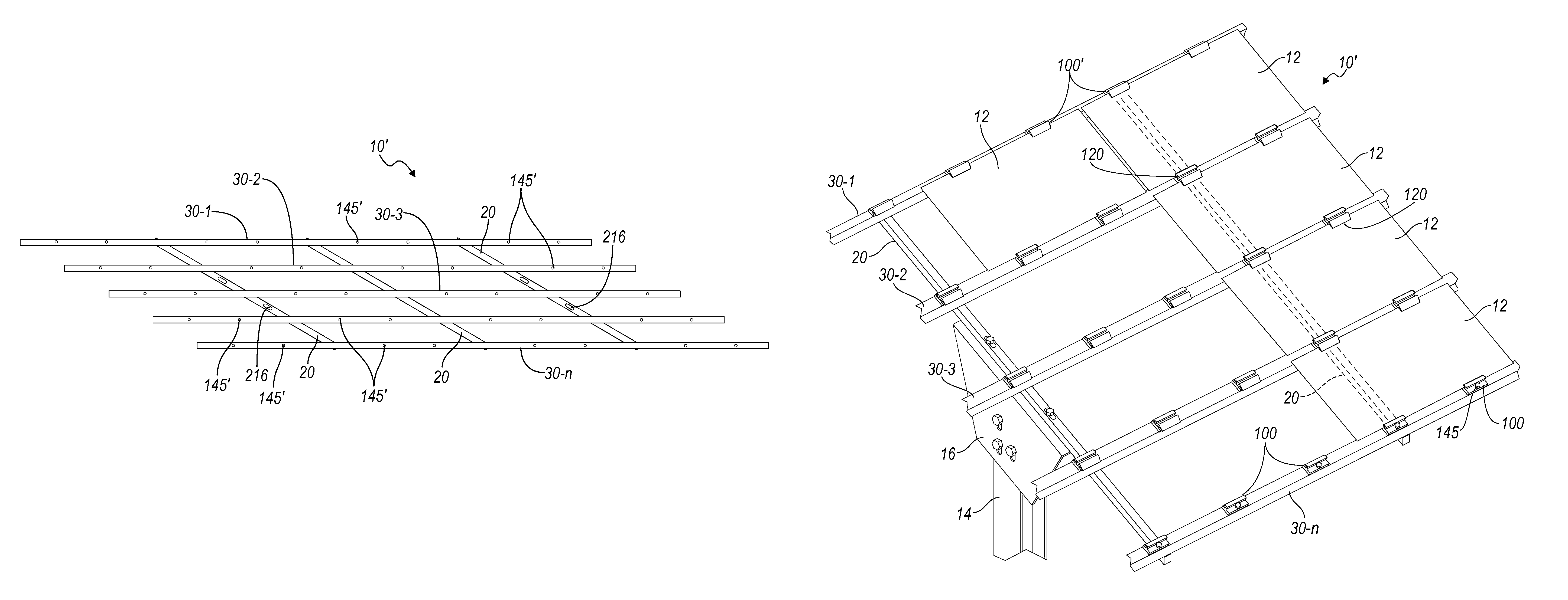
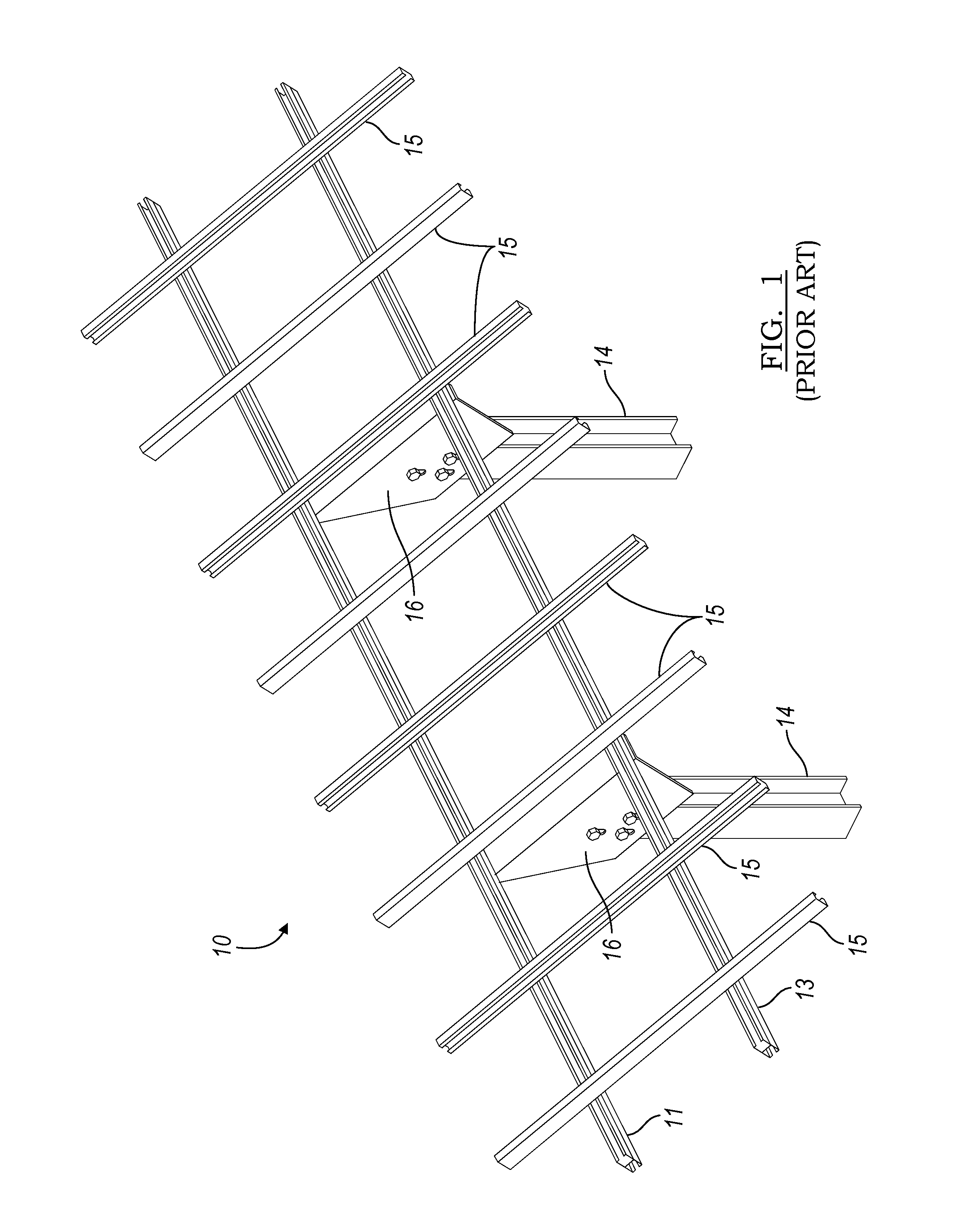
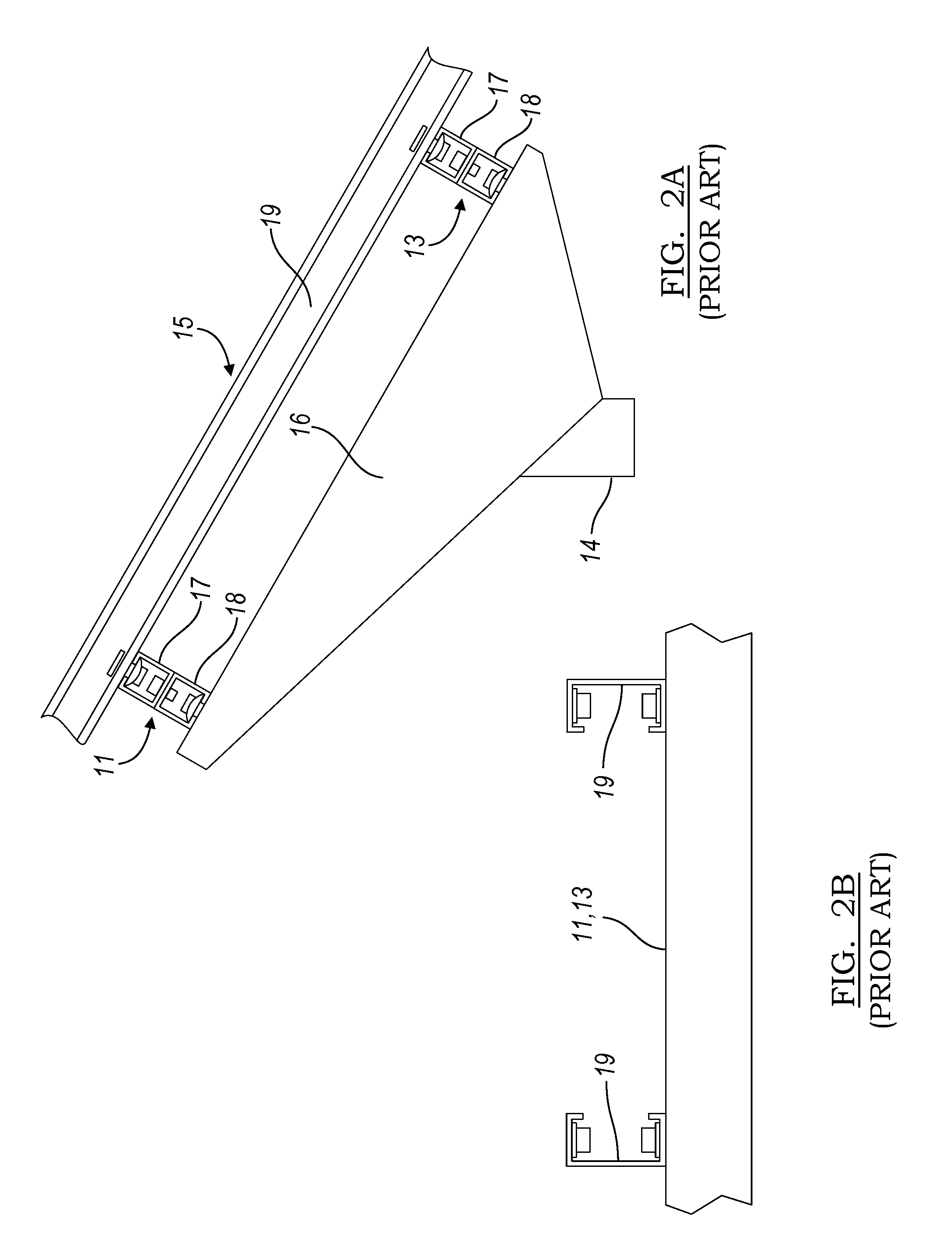
[0052]With reference to the drawings, a support system for a photovoltaic array of framed or unframed solar panels 12, 12′, respectively, known in the prior art includes a free ground rack structure having spaced vertical support elements 14 extending from the ground. The support system 10 of FIG. 1 shows only two vertical support elements 14, although multiple support elements may be used to accommodate a longer array of solar panels. Notably, the support system can also be mounted to a roof (or other structure), or tracking unit. Each of the support elements 14 for the free-field ground rack is preferably an I-beam securely embedded and vertically aligned in the ground, as is well known in the art.

[0053]Conventionally, a pair of lower horizontally-aligned, C-shaped support joists 11, 13 is mounted at the upper ends of the support elements 14 by tilt bracket mounts 16. Thus, the vertical support elements 14 are spanned by the support joists 11, 13. When there are additional arrays ...


PUM

PropertyMeasurementUnit
longitudeaaaaaaaaaa
torqueaaaaaaaaaa
lengthaaaaaaaaaa

Abstract

Precise parameters are maintained in a support structure for solar panels or other panel-like structures through use of a collapsible folding structure which is preassembled to precise tolerances at a convenient staging site before being collapsed for shipment. Easy installation with unskilled labor is facilitated by attaching one support joist to a substrate and then unfolding the entire support structure.

Description

PRIORITY INFORMATION[0001]The present invention claims priority to U.S. patent application Ser. No. 12 / 383,240 filed on Mar. 20, 2009, and makes reference herein to same in its entirety.FIELD OF THE INVENTION[0002]This invention relates to a solar energy collection system, and more particularly to a support system for an array of photovoltaic panels and method of assembling the same. The invention includes a bi-directional span of support members, including a profiled support rail having a longitudinal T-slot channel adapted to receive the head of a bolt for adjustable attachment to a support joist. A variety of panel-holding devices, such as friction clips, may also be used.BACKGROUND OF THE INVENTION[0003]A standard photovoltaic panel array includes a plurality of solar panels optimally arranged for converting light incident upon the panels to electricity. Various support systems are used for attachment to roofs, free-field ground racks or tracking units. Typically, these support ...

Claims


Application Information

Patent Timeline
Patent Type & Authority Patents(United States)
IPC IPC(8): E04D13/18E04D13/035
CPCF24J2/465F24J2/5232F24J2/5252F24J2/526H02S20/00Y02E10/47Y10T29/49616F24J2002/5277F24J2002/5281Y02B10/12Y02E10/50F24J2002/5215F24S25/12F24S25/63F24S25/65F24S80/70F24S2025/012F24S2025/014F24S2025/801H02S20/10H02S20/23H02S20/30Y02B10/10
Inventor CUSSON, PAUL R.VOYTILLA, ROBERT J.
Owner NORTHERN STATES METALS CO
Why Eureka
Try Eureka