Visual navigation system and method based on structured light

a navigation system and structured light technology, applied in the field of visual navigation system, can solve the problems of inability to obtain, inability to anticipate or identify dynamically changing environments, and inability to diversify the environment-sensing capability of robots, so as to reduce the operation burden of the visual server and increase the accuracy of robot navigation

Active Publication Date: 2012-08-14
IND TECH RES INST
View PDF13 Cites 25 Cited by
  • Summary
  • Abstract
  • Description
  • Claims
  • Application Information

AI Technical Summary

Benefits of technology

[0016]A visual navigation system and method based on structured light are provided. The visual navigation system at least includes at least one projector for generating a specific path pattern formed by structured light, and a visual server. In addition to facilitating the visual navigation system to detect an obstacle, the pattern formed by the structured light provides a specific path pattern followed by robots during the navigation. In the visual navigation method, when detecting the obstacle, the visual server routes a virtual path and issues a movement-control command to the robots, which in turn follow the virtual path. The present invention is capable of raising the accuracy for the robot navigation and reducing operation burden of the visual server by using the structured light to guide the robots.

Problems solved by technology

At present, the biggest bottleneck for the navigation technique is that, during the navigation, the robots usually cannot anticipate or identify a dynamically changing environment.
Furthermore, since the data obtained by sensors is usually incomplete, discontinuous, and unreliable, the environment-sensing capability of the robots is diversified but not robust.
For example, an ultrasonic sensor has a large sensing angle, a low resolution, but cannot obtain the specific shape of an obstacle; and, an infrared sensor is easily interfered by the surface characteristics of the obstacle.
Currently, multi-sensing modes are combined to eliminate disadvantages of a single sensor, but the complexity of the system is accordingly increased and the power consumption is increased as well.
In the applications of in-door robots, for example, clean-service robots, the aforementioned navigation method may reduce the overall navigation efficiency due to the image processing, which is also unsatisfied in evading obstacles.
However, the floor material adopted by the patent should be particularly manufactured, which has a high cost and easily damaged to cause the failure of the navigation.
Moreover, the floor material may even be seriously damaged to cause the robot to sink therein and result in malfunctions.
Although the robot navigation methods provided by the above two patents can solve a part of the navigation problems, as for in-door service robots, the following problems still exist.
2. The operations for determining the position of an obstacle and routing a path are rather time-consuming, and an over-high operation ratio of the visual servo may seriously influence the instantaneity of the servo control.
3. All the paths are formed through using a visual servo, and the tracking of the robots is of an excessively low precision at far away positions in the image.
4. The wandering paths for autonomously moving robots are repeated, which wastes time and power.
5. An additional visual servo system usually needs to be constructed in the environment, which may affect the original layout and raise the cost of the system.

Method used


Image

  • Visual navigation system and method based on structured light
  • Visual navigation system and method based on structured light
  • Visual navigation system and method based on structured light

Examples


first embodiment

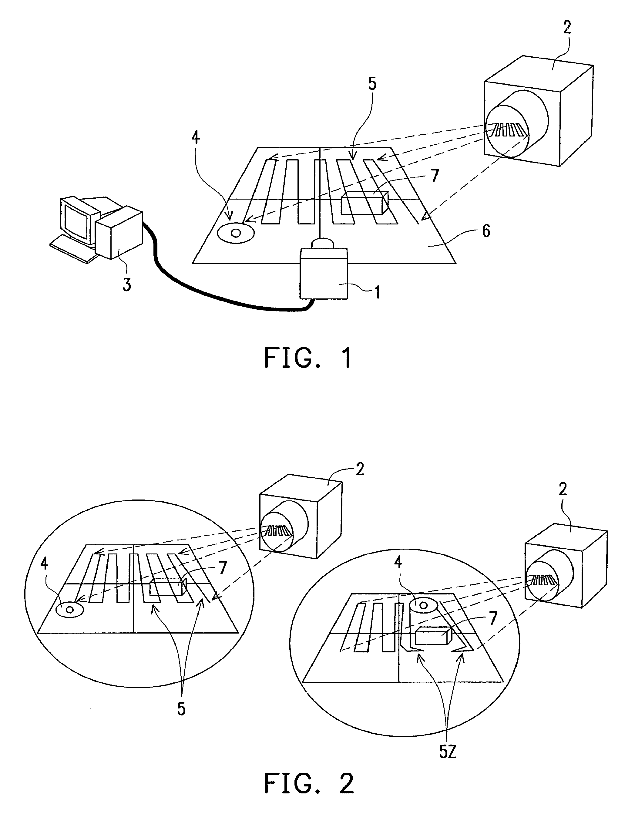
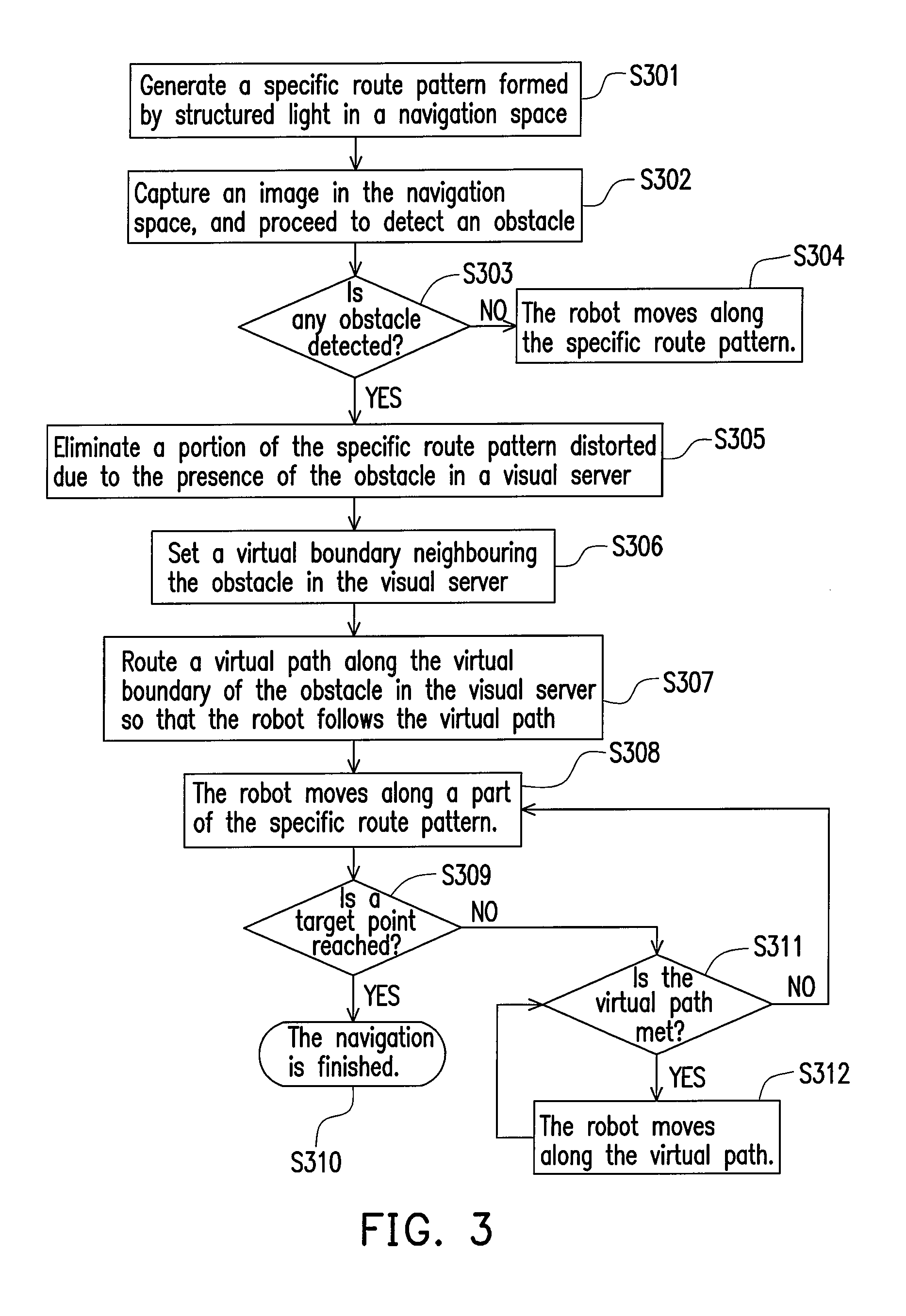
[0027]First of all, a “robot” here is defined as a mobile platform capable of carrying out a particular task. Such a platform, no matter driven by wheels (or referred to as a wheeled vehicle) or moving on foot, is called a robot. Then, referring to FIG. 1, the present invention is shown, and the visual navigation system based on structured light includes an image capture device 1, such as a digital camera, a projector 2, a visual server 3, and a robot 4. The projector 2 projects the structured light for forming a specific path pattern 5 into a navigation space 6 where the robot 4 requires a navigation path, and the structured light may be a visible light or invisible light. Meanwhile, the structured light may be generated continuously, or intermittently, or only once. The robot 4 senses the specific path pattern through an optical sensor or an image sensor, and thus the robot 4 is capable of moving along the specific path pattern 5. The image capture device 1 captures an image in th...

second embodiment

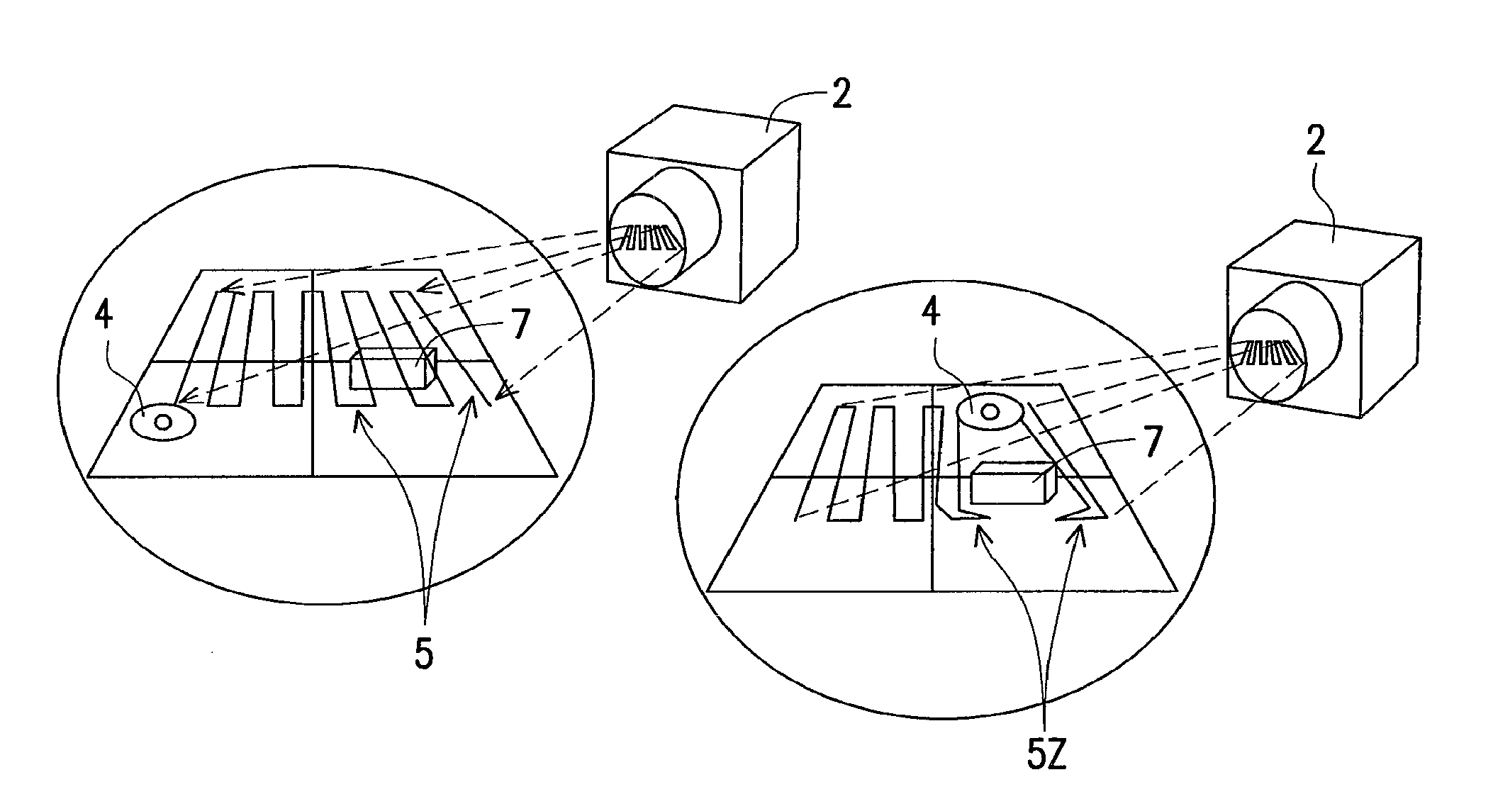
[0029]FIG. 4 shows the present invention. The visual navigation system based on structured light includes an image capture device 1, a projector 2a and another projector 2b, a visual server 3, and a robot 4. The projector 2a is constructed opposite to the projector 2b. The projectors 2a, 2b respectively project specific path patterns 5a, 5b overlapped with each other into the navigation space 6 where the robot 4 requires a navigation path. The specific path patterns 5a, 5b together form a combined path pattern large enough for covering the navigation space around the obstacle 7, such that the obstacle 7 does not block the projection of the structured light due to its own volume to result in a region without the combined path pattern nearby. In order to enable the robot 4 to identify that the path it follows is the path pattern 5a or 5b, each of the specific path patterns 5a, 5b has structured light of a different colour, for example, red or blue, such that the robot 4 moves along a ...

third embodiment

[0031]FIG. 5 shows the present invention. The visual navigation system based on structured light includes an image capture device 1, a projector 2c and another projector 2d, a visual server 3, and a robot 4. The projectors 2c and 2d may be independent devices or they may be connected to each other via a mechanism. The two projectors 2c and 2d respectively project specific path patterns 5c, 5d into a navigation space 6 where the robot 4 requires a navigation path. The image capture device 1 captures an image in the navigation space and then transmits the image to the visual server 3 to be processed. It is clearly seen from FIG. 5 that, the regions in the navigation space 6 where the projectors 2c, 2d intend to project thereon are not overlapped with each other, so the specific path patterns 5c, 5d are not overlapped with each other as well. If the specific path patterns are not overlapped with each other, the projectors respectively project towards the same region in the navigation s...


PUM

PropertyMeasurementUnit
volumeaaaaaaaaaa
distanceaaaaaaaaaa
coloraaaaaaaaaa

Abstract

A visual navigation system and method based on structured light are provided. The visual navigation system at least includes at least one projector for generating a specific path pattern formed by structured light, and a visual server. In addition to facilitating the visual navigation system to detect an obstacle, the pattern formed by the structured light provides a specific path pattern followed by robots during the navigation. In the visual navigation method, when detecting the obstacle, the visual server routes a virtual path and issues a movement-control command to the robots, which in turn follow the virtual path. The present invention is capable of raising the accuracy for the robot navigation and reducing operation burden of the visual server by using the structured light to guide the robots.

Description

CROSS-REFERENCE TO RELATED APPLICATION[0001]This application claims the priority benefit of Taiwan application serial no. 96141656, filed on Nov. 5, 2007. The entirety of the above-mentioned patent application is hereby incorporated by reference herein and made a part of this specification.BACKGROUND OF THE INVENTION[0002]1. Field of the Invention[0003]The present invention relates to a visual navigation system and a method thereof. More particularly, the present invention relates to a visual navigation system and method capable of guiding robots by use of structured light.[0004]2. Description of Related Art[0005]Recently, with the rapid progress of sensors and control theories, an intelligent robot system originally employed in an automatic factory field has been gradually applied to various service applications, which opens up a new field of robot autonomous services. The research and development of service robots are mainly carried out by academic institutions in the past, but no...

Claims


Application Information

Patent Timeline
Patent Type & Authority Patents(United States)
IPC IPC(8): G05D5/00B23K9/127
CPCG05D1/0246
Inventor LIN, YEN-CHUNCHEN, YAO-JIUNNWU, CHAO-CHI
Owner IND TECH RES INST
Why Eureka
Try Eureka