Burner ring

a burner ring and burner technology, applied in the field of burner rings, can solve problems such as uneven distribution

Active Publication Date: 2012-08-21
BSH BOSCH & SIEMENS HAUSGERAETE GMBH
View PDF16 Cites 7 Cited by
  • Summary
  • Abstract
  • Description
  • Claims
  • Application Information

AI Technical Summary

Benefits of technology

[0005]The object of the invention is hence to provide a possibility for realizing a ...

Problems solved by technology

Conversely, in the prior art according to DE 41 25 308 A1 a substantial portion of the gas stream entering the gas conducting...

Method used


Image

  • Burner ring
  • Burner ring
  • Burner ring

Examples


Embodiment Construction

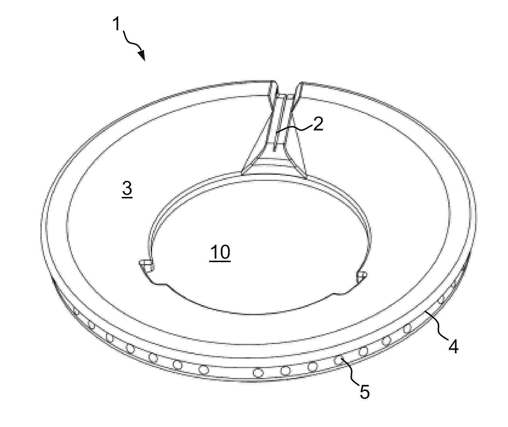
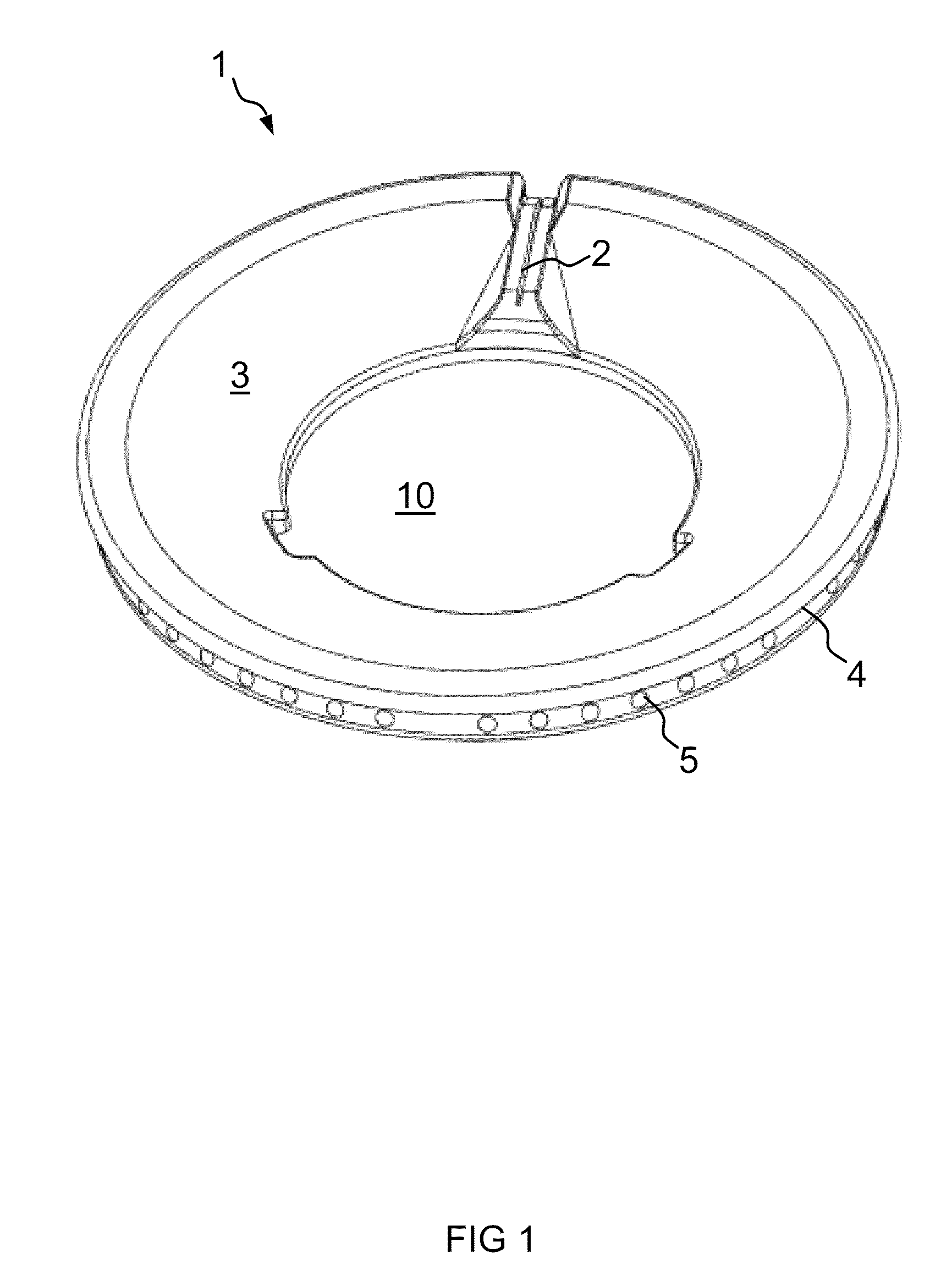
[0024]FIG. 1 is an oblique top view of a burner ring 1 for a two-ring gas burner in the direction of a transfer ignition groove 2. The upwardly open transfer ignition groove 2 connects an inner circumference 3 of the burner ring 1 to an outer circumference 4 of the burner ring 1. The outer circumference 4 is furnished with gas outlets 5 connected to a distribution chamber (not shown) arranged in a circular manner in the burner ring 1. The inner circumference 3 of the burner ring 1 when mounted in a gas burner surrounds an inner region of the gas burner while the gas outlets 5 on the outer circumference 4 produce the main flame.

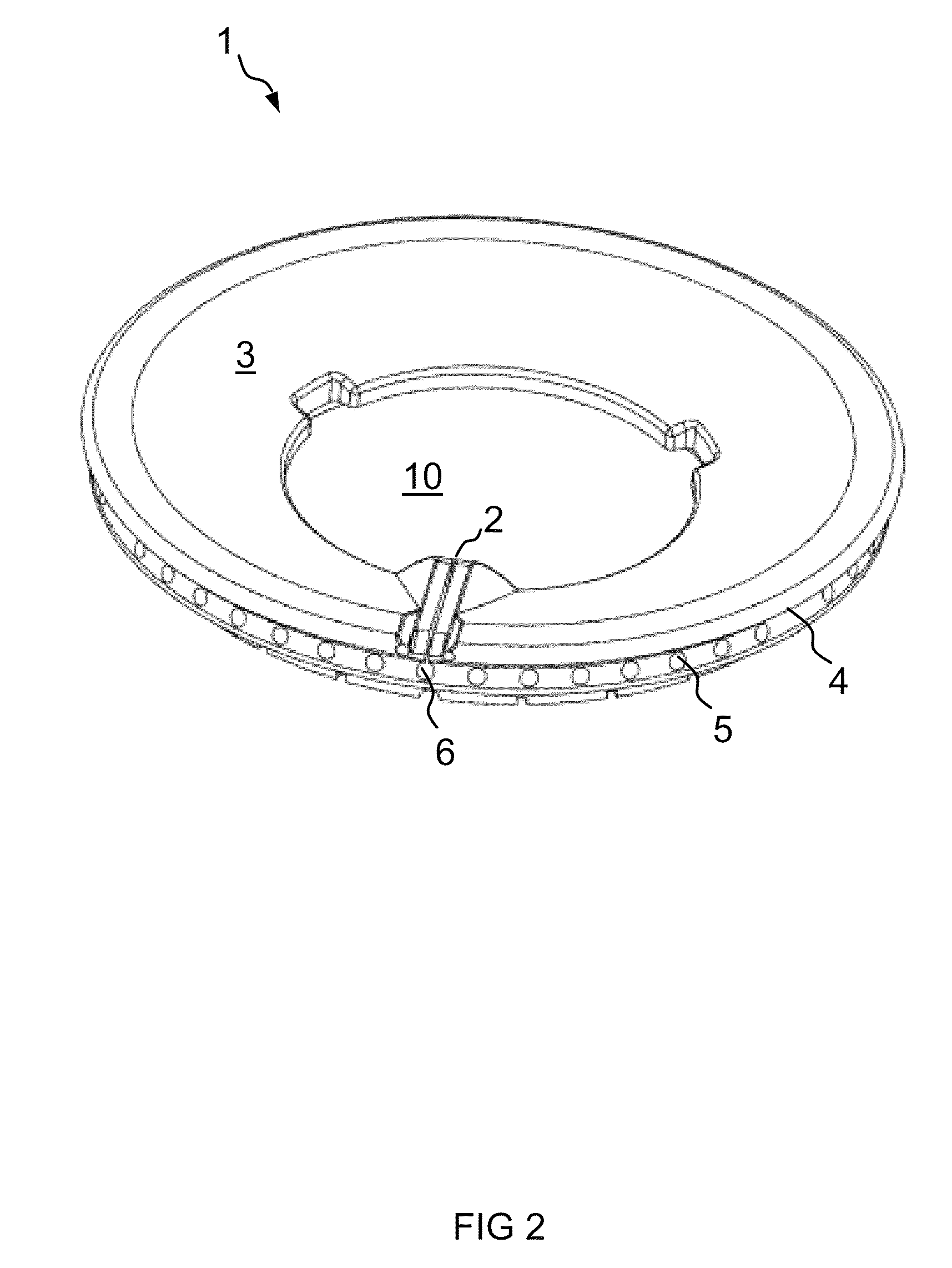
[0025]FIG. 2 is an oblique top view of the burner ring 1 shown in FIG. 1 from an opposite perspective. Shown in addition to the elements illustrated in FIG. 1 is a gas conducting channel 6 in the form of a drilled hole into which the transfer ignition groove 2 opens downwardly. The gas conducting channel 6 and transfer ignition groove 2 are arranged mutually s...


PUM


Abstract

A burner ring for a gas burner, the burner ring including an outer circumference and an inner circumference, a distribution chamber having gas outlets to the outer circumference of the burner ring, a transfer ignition groove that is outwardly open on one side and extends between the inner circumference of the burner ring and the outer circumference of the burner ring, a gas conducting channel into which the transfer ignition groove opens at least partially, and at least one gas supply opening between the distribution chamber and the gas conducting channel, wherein the gas conducting channel and the transfer ignition groove are arranged mutually symmetrically, and wherein the at least one gas supply opening is offset in a region of the gas conducting channel at an angle relative to the transfer ignition groove.

Description

[0001]The invention relates to a burner ring for gas burners that has a distribution chamber having gas outlets to the burner ring's outer circumference, and further has a transfer ignition groove that is outwardly open on one side and extends between an inner circumference of the burner ring and the burner ring's outer circumference, a gas conducting channel into which the transfer ignition groove opens at least partially, and at least one gas supply opening between the distribution chamber and gas conducting channel. The invention relates further to a gas burner having a burner ring of such type, with the burner ring surrounding an inner region of the gas burner and the gas outlets producing the main flame on the outer circumference. In particular an ignition plug and a thermoelement can be located in the inner region.BACKGROUND OF THE IVENTION[0002]Burner rings having simple transfer ignition grooves are known from, for instance, WO 02 / 25170, DE 200 16 506 U1, and DE 200 19 731 U...

Claims


Application Information

Patent Timeline
IPC IPC(8): F23D14/06
CPCF23D14/06F23D2900/14062
Inventor CADEAU, CHRISTOPHENAUMANN, JORN
Owner BSH BOSCH & SIEMENS HAUSGERAETE GMBH
Why Eureka
Try Eureka