High voltage transmit/receive switch and method therefor

a transmit/receive switch, high-voltage technology, applied in the direction of electrical equipment, instruments, arrangements responsive to excess voltage, etc., can solve the problems of increasing the number of components, creating power consumption concerns, and affecting the layout of printed circuit boards, and achieve constant resistance characteristics.

Active Publication Date: 2012-08-28
MICROCHIP TECH INC
View PDF1 Cites 11 Cited by
  • Summary
  • Abstract
  • Description
  • Claims
  • Application Information

AI Technical Summary

Benefits of technology

[0009]A two terminal high voltage transmit and receive protection switch has a constant resistance characteristic when small signals, amplitudes within approximately −300 mV and +300 mV, are applied and a low constant current source characteristic when high voltages, amplitudes more positive than approximately +2.0V and more negative than approximately −2.0V, are applied.

Problems solved by technology

For a system having 128 channels or even more will create a power consumption concern.
The component count also creates problems for the printed circuit board layout as it consume a lot of area and must be strategically placed to minimize electric noise.

Method used


Image

  • High voltage transmit/receive switch and method therefor
  • High voltage transmit/receive switch and method therefor
  • High voltage transmit/receive switch and method therefor

Examples


Embodiment Construction

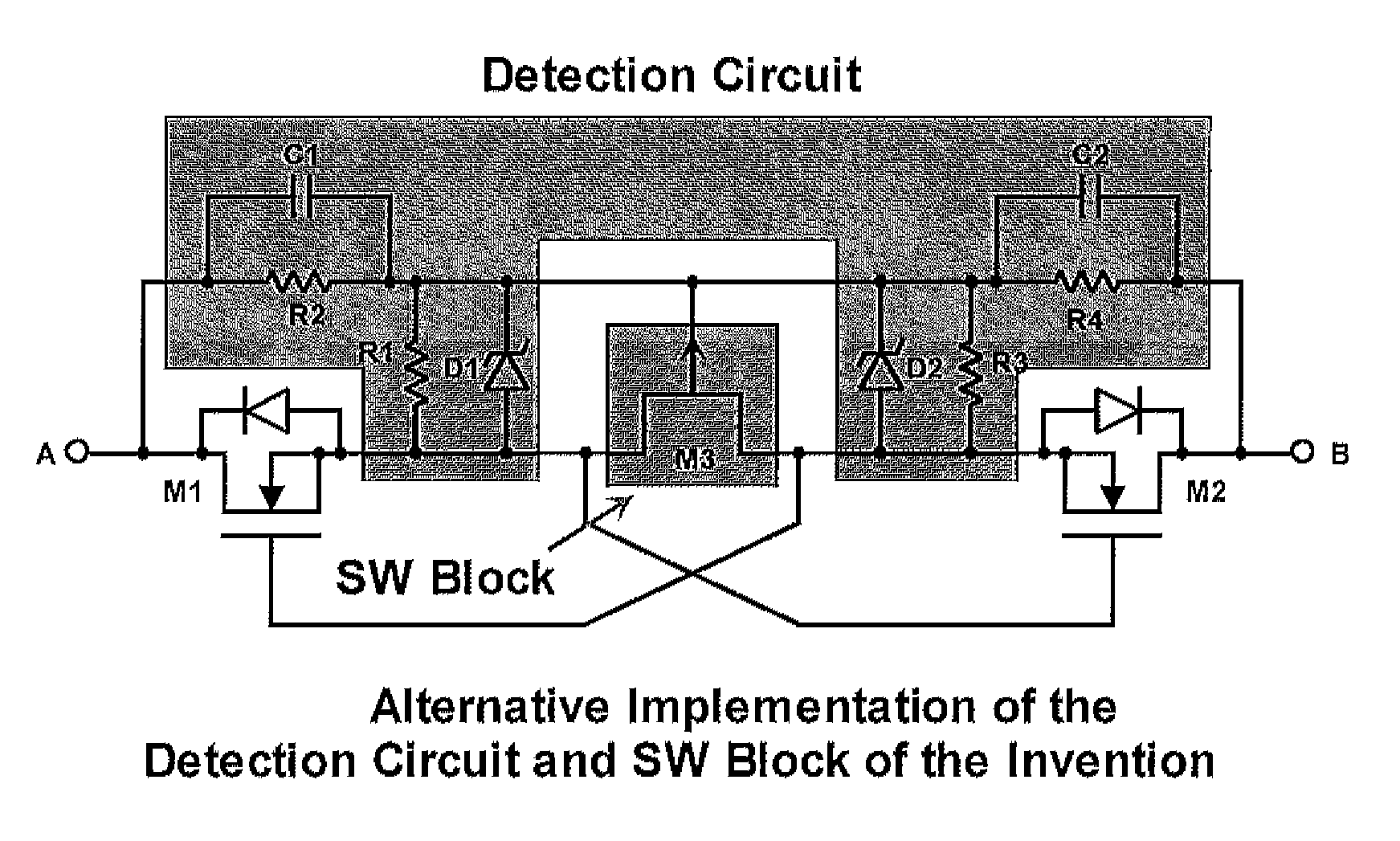
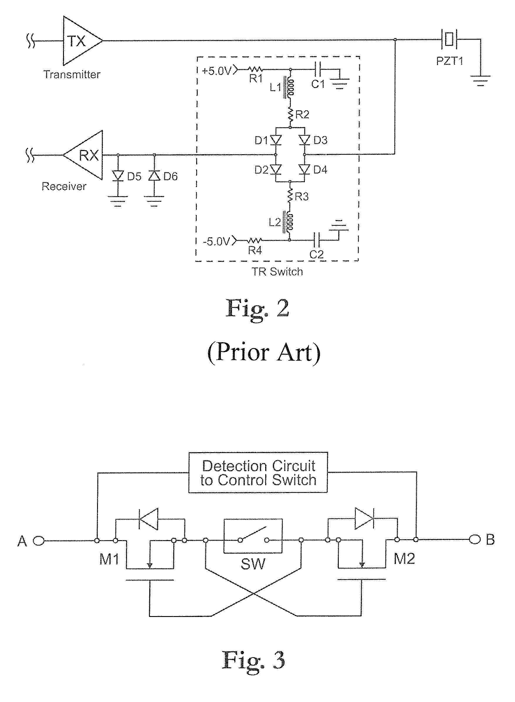
[0021]Referring to FIG. 3, one embodiment of a TR switch 100 is shown. In general, the TR Switch 100 has two modes of operation; 1) protection mode and 2) receive mode. In the protection mode, the TR Switch 100 should protect a low voltage low noise receiver amplifier against the high voltage transmit pulses. This may have to occur quickly because the transmit pulses are generally high frequency and high voltage. In the receive mode, the TR switch resistance should be fairly constant to minimize any distortion. The TR switch 100 further should minimize any parasitic capacitances to any AC ground path that would attenuate the signal, and further should minimize any electrical noise that may be introduced. The TR switch 100 should automatically switch from protection mode to receive mode with minimal external command control signals or power supplies. The TR switch 100 further should protect against both positive and negative voltages.

[0022]As shown in FIG. 3 a simplified circuit diag...


PUM


Abstract

A two terminal transmit receive device passes small analog signals with a constant low resistance value to the input of a low noise, low voltage receiver amplifier and can protect the input against the high voltage transmit signals in ultrasound applications without the aid of any power supplies. The device uses depletion-mode transistors that are normally on to pass small analog signal and a voltage detection circuit that quickly turns off the depletion-mode transistors when the presence of high voltage is detected.

Description

RELATED APPLICATIONS[0001]This application claims the benefit of U.S. Provisional Application No. 61 / 175,848 filed May 6, 2009, which is incorporated herein by reference in their entirety.FIELD OF THE INVENTION[0002]The invention relates to a transmit / receive switch and, more specifically, to a transmit / receive switch used to protect a low noise low voltage receiver against high voltage transmit pulses while in transmit mode and allowing small analog signals to pass into the low noise low voltage receiver while in receive mode in an ultrasound imaging application.BACKGROUND OF THE INVENTION[0003]The fundamental principle of ultrasound imaging is to use acoustic waves to help image an object. The basic blocks for ultrasound imaging is the use of an array 10 of piezoelectric transducers (T) in which each transducer will require a high voltage transmitter block (TX), a transmit / receive switch block (T / R Switch), and a low noise receiver block (RX) as shown in FIG. 1.[0004]In each trans...

Claims


Application Information

Patent Timeline
Patent Type & Authority Patents(United States)
IPC IPC(8): H02H3/20H02H9/04
CPCG01S7/52017
Inventor CHOY, BENEDICT C. K.LEI, JIMES
Owner MICROCHIP TECH INC
Why Eureka
Try Eureka