Closure for rod receiving orthopedic implant having left handed thread removal

a technology for orthopedic implants and closures, applied in the field of closures for rods receiving orthopedic implants having left handed thread removal, can solve the problems of implant special problems, difficult to solve, and medical implants present a number of problems to both surgeons, and achieve the effects of low or minimal profile, enhanced setting engagement of closures, and low manufacturing cos

Active Publication Date: 2012-09-04
JACKSON ROGER P
View PDF450 Cites 15 Cited by
  • Summary
  • Abstract
  • Description
  • Claims
  • Application Information

AI Technical Summary

Benefits of technology

[0039]Therefore, objects of the present invention include providing an improved closure plug or closure top for use with an open headed bone screw; providing such a closure having a cylindrical base and a driving or installation head that breaks away from the base at a breakaway region to provide a low or minimized profile subsequent to installation of the closure; providing such a closure having removal structure enabling positive, non-slip engagement of the closure by a removal tool which securely grips and holds the closure; providing such a closure having an axially extending bore that passes through the installation head and at least into the closure; providing such a closure in which the bore has an internal left handed thread that is sized and shaped to receive a removal tool with a matingly threaded projection; providing such a closure in combination with an open headed bone implant screw for use in anchoring a bone fixation structural member, such as a rod; providing such a closure combination in which the open headed bone screw includes a pair of spaced apart arms forming a rod receiving channel; providing such a closure combination including an external guide and advancement flange on the closure and mating internal guide and mating structure on inner surface...

Problems solved by technology

Medical implants present a number of problems to both surgeons installing the implants and to engineers designing them.
These are normally conflicting goals and often difficult to resolve.
One particular type of implant presents special problems.
While the closed headed devices are highly effective at capturing and securing a rod, it is very difficult during surgery to insert the rod through the heads, since the rod must be introduced through an opening in the head.
Consequently, the more screw heads that the rod must pass through, the more difficult it is to manipulate the rod into and through them.
While the open headed devices are often necessary and often preferred for usage, there is a significant problem associated with them.
Forces applied during installation or during accidents can cause the arms to splay or spread at the top which may result in failure of the implant if the arms splay sufficiently to loosen or release the closure.
The closure can be of a slide in type, but such are not easy to use.
Such nuts prevent splaying of the arms, but nuts substantially increase the size and profile of the implant which is not desirable.
However, threaded plugs have encountered problems also in that they especially produce forces that are radially outward directed and that lead to splaying or spreading of the arms or at least do not prevent splaying due to other causes that in turn loosens or completely releases the rod relative to the implant.
But, as noted above, conventional V-shaped threaded plugs exert radially outward forces and tend to splay or push the upper ends of the arms radially outward upon the application of a significant amount of torque, which ends up bending the arms relative to a body sufficiently to allow the threads to loosen or disengage from each other and the closure to loosen and/or disengage from the implant and thereby ...

Method used


Image

  • Closure for rod receiving orthopedic implant having left handed thread removal
  • Closure for rod receiving orthopedic implant having left handed thread removal
  • Closure for rod receiving orthopedic implant having left handed thread removal

Examples


Embodiment Construction

[0051]As required, detailed embodiments of the present invention are disclosed herein; however, it is to be understood that the disclosed embodiments are merely exemplary of the invention, which may be embodied in various forms. Therefore, specific structural and functional details disclosed herein are not to be interpreted as limiting, but merely as a basis for the claims and as a representative basis for teaching one skilled in the art to variously employ the present invention in virtually any appropriately detailed structure.

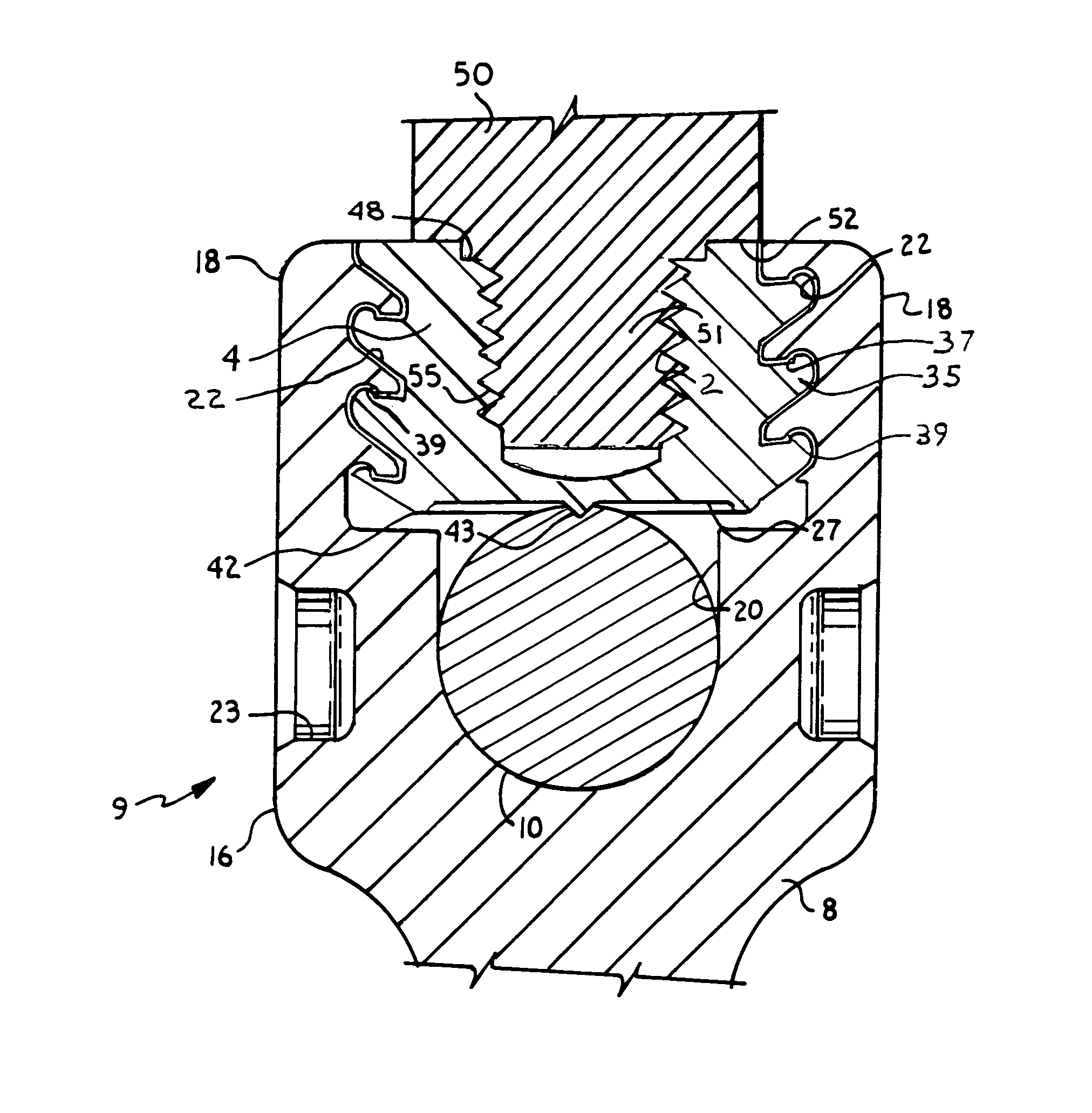
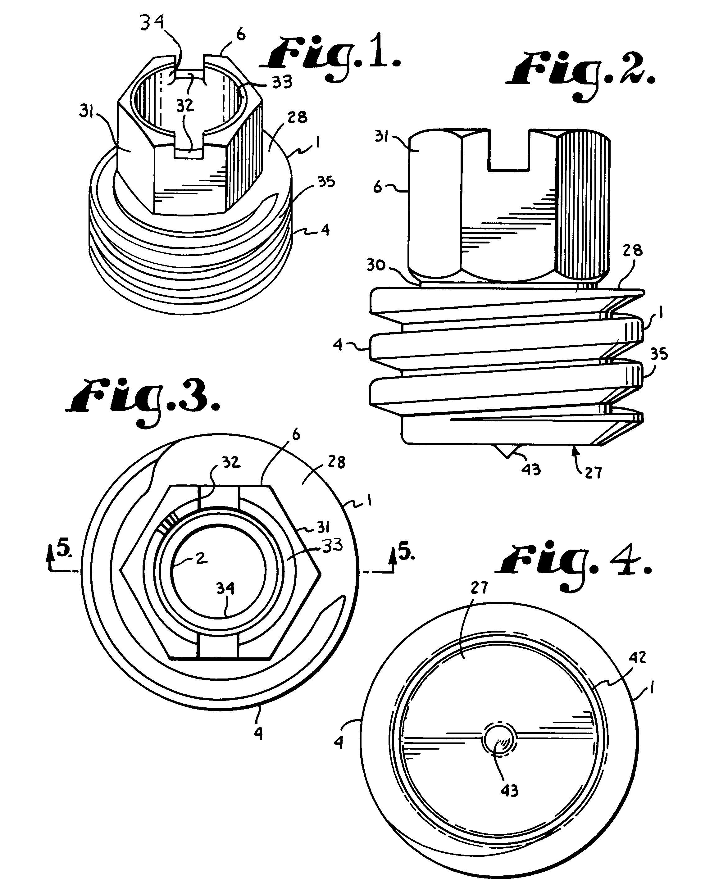
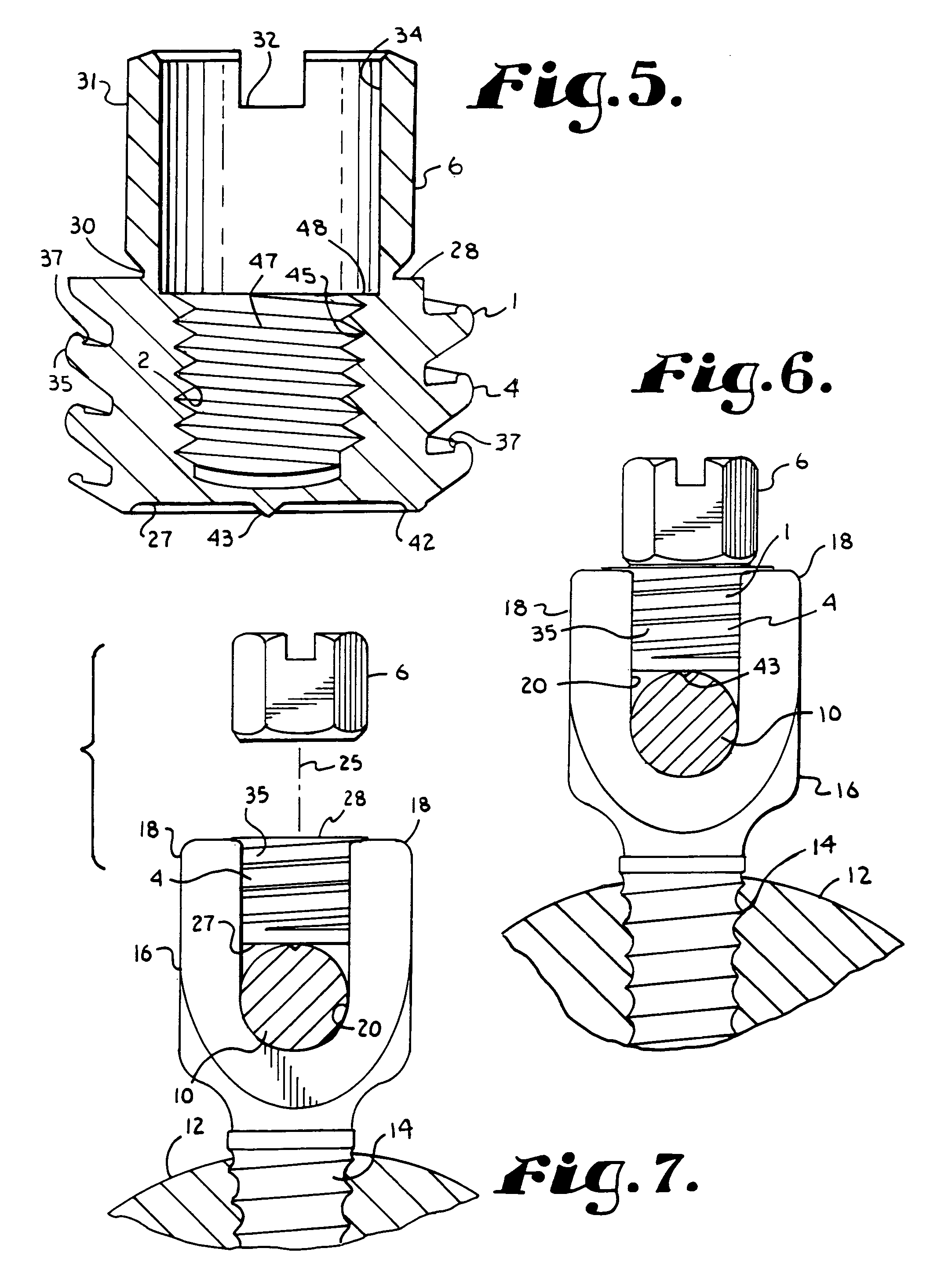
[0052]Referring to the drawings in more detail, the reference numeral 1 generally designates an anti-splay closure with a partial axial bore 2. The closure 1 generally includes a closure plug or body 4 and a breakaway head 6 for installation. The closure 4 is used in cooperation with an open headed bone implant screw 8 (FIGS. 6 and 7) to form an implant anchor assembly 9 to secure or anchor a spinal fixation member or rod 10 with respect to a bone 12, such as...


PUM


Abstract

An anti-splay closure with a left handed threaded removal bore, includes a cylindrical closure body with an external, continuous, helically extending anti-splay guide and advancement flange and a breakaway installation head. The removal bore is aligned with an axis of the closure body. The bore thread is sized and shaped to receive a removal tool having mating left handed thread. The closure is used with an open headed bone implant screw which is provided with internal, helically extending mating guide and advancement structure complementary to the flange of the closure body.

Description

CROSS-REFERENCE TO RELATED APPLICATION[0001]This is a continuation-in-part of U.S. patent application, Ser. No. 10 / 236,123 filed Sep. 6, 2002 for HELICAL WOUND MECHANICALLY INTERLOCKING MATING GUIDE AND ADVANCEMENT STRUCTURE, which is now U.S. Pat. No. 6,726,689.BACKGROUND OF THE INVENTION[0002]The present invention is directed to a closure for operably securing a rod to an orthopedic implant wherein said closure includes a break off head, a left hand threaded axially aligned bore for use in removal of the closure from the implant and a structure for use in interlocking together the closure and the implant. The interlocking structure includes a first interlocking form on the closure and a mating second interlocking form on the implant. The closure is operably rotated into the implant and against the rod for securing the rod in the implant. The first and second interlocking forms are both helically wound so that the first interlocking form advances relative to the second interlocking...

Claims


Application Information

Patent Timeline
IPC IPC(8): A61B17/70A61B17/00A61B17/86A61B17/88A61B19/00F16B31/02F16B33/02F16B35/04
CPCA61B17/7032A61B17/7091F16B31/021F16B35/047A61B2017/8655A61B2019/307F16B33/02F16B2033/025A61B2090/037
Inventor JACKSON
Owner JACKSON ROGER P
Why Eureka
Try Eureka