Integration of a vertical cavity surface emitting laser (VCSEL) on an energy-assisted magnetic recording (EAMR) head

a technology of energy-assisted magnetic recording and laser, which is applied in the field of integration of vertical cavity surface emitting laser (vcsel) on an energy-assisted magnetic recording (eamr) head, can solve the problems of increasing coercivity, increasing the cost and complexity of integrating laser light, and reducing grain size soon reaches the “superparamagnetic limit”

Active Publication Date: 2012-09-04
WESTERN DIGITAL TECH INC
View PDF31 Cites 156 Cited by
  • Summary
  • Abstract
  • Description
  • Claims
  • Application Information

AI Technical Summary

Benefits of technology

[0005]Various embodiments of the present invention solve the foregoing problem by providing an energy-assisted magnetic recording apparatus in which VCSELs are bonded to corresponding magnetic recording heads during wafer processing. This approach provides a reliable heat source for EAMR using reliable wafer bonding techniques, and greatly reduces the cost and complexity of integrating laser light into an EAMR system.

Problems solved by technology

This reduction in grain size soon reaches a “superparamagnetic limit,” at which point the magnetic grains become thermally unstable and incapable of maintaining their magnetization.
Increasing the magnetic anisotropy of the magnetic grains, however, increases their coercivity and therefore requires a stronger magnetic field to change the magnetic orientation of the grains (e.g., in a write operation).
This approach requires a semiconducting wafer or some semiconducting materials (e.g., GaAs and AlGaAs) for fabricating the slider, which would complicate the magnetic head fabrication process and would greatly increase the cost of the slider.
This approach might require integrating and aligning multiple optical fibers and other optical components into a laser-slider assembly, which would also increase the cost and time required to produce the magnetic recording head.

Method used


Image

  • Integration of a vertical cavity surface emitting laser (VCSEL) on an energy-assisted magnetic recording (EAMR) head
  • Integration of a vertical cavity surface emitting laser (VCSEL) on an energy-assisted magnetic recording (EAMR) head
  • Integration of a vertical cavity surface emitting laser (VCSEL) on an energy-assisted magnetic recording (EAMR) head

Examples


Embodiment Construction

[0015]In the following detailed description, numerous specific details are set forth to provide a full understanding of the present invention. It will be apparent, however, to one ordinarily skilled in the art that the present invention may be practiced without some of these specific details. In other instances, well-known structures and techniques have not been shown in detail to avoid unnecessarily obscuring the present invention.

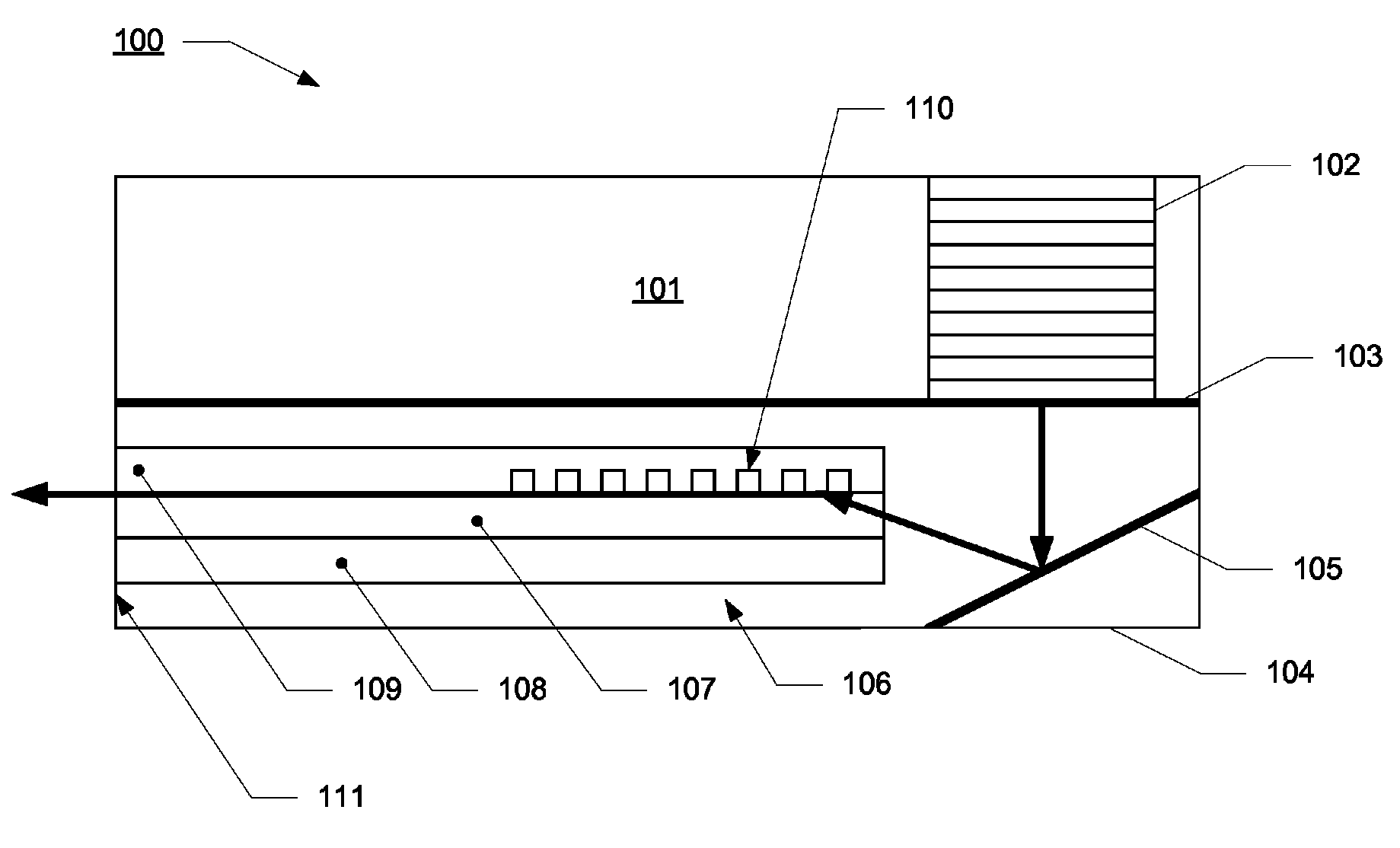
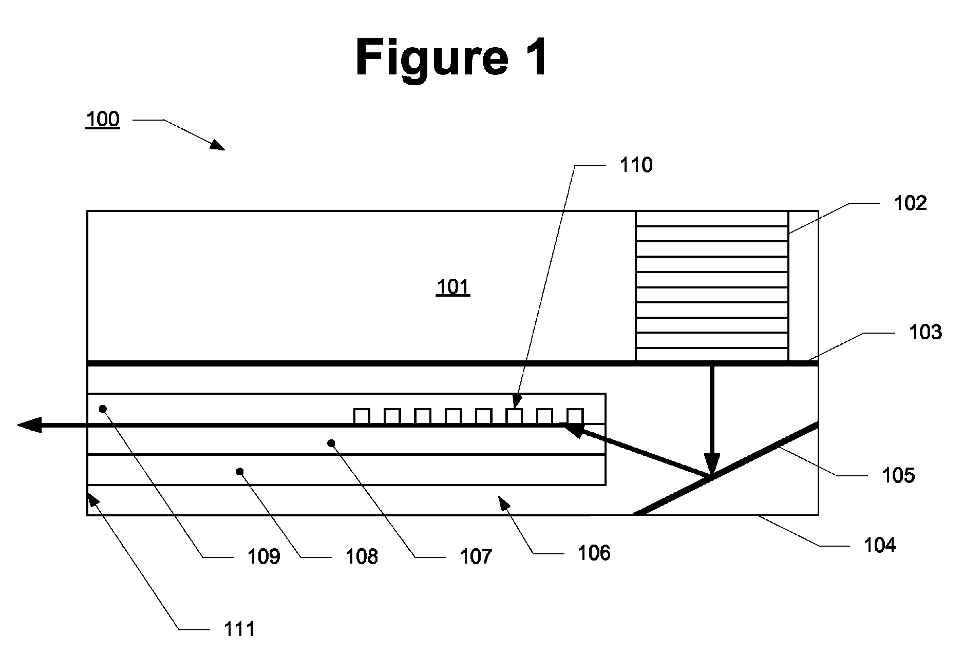
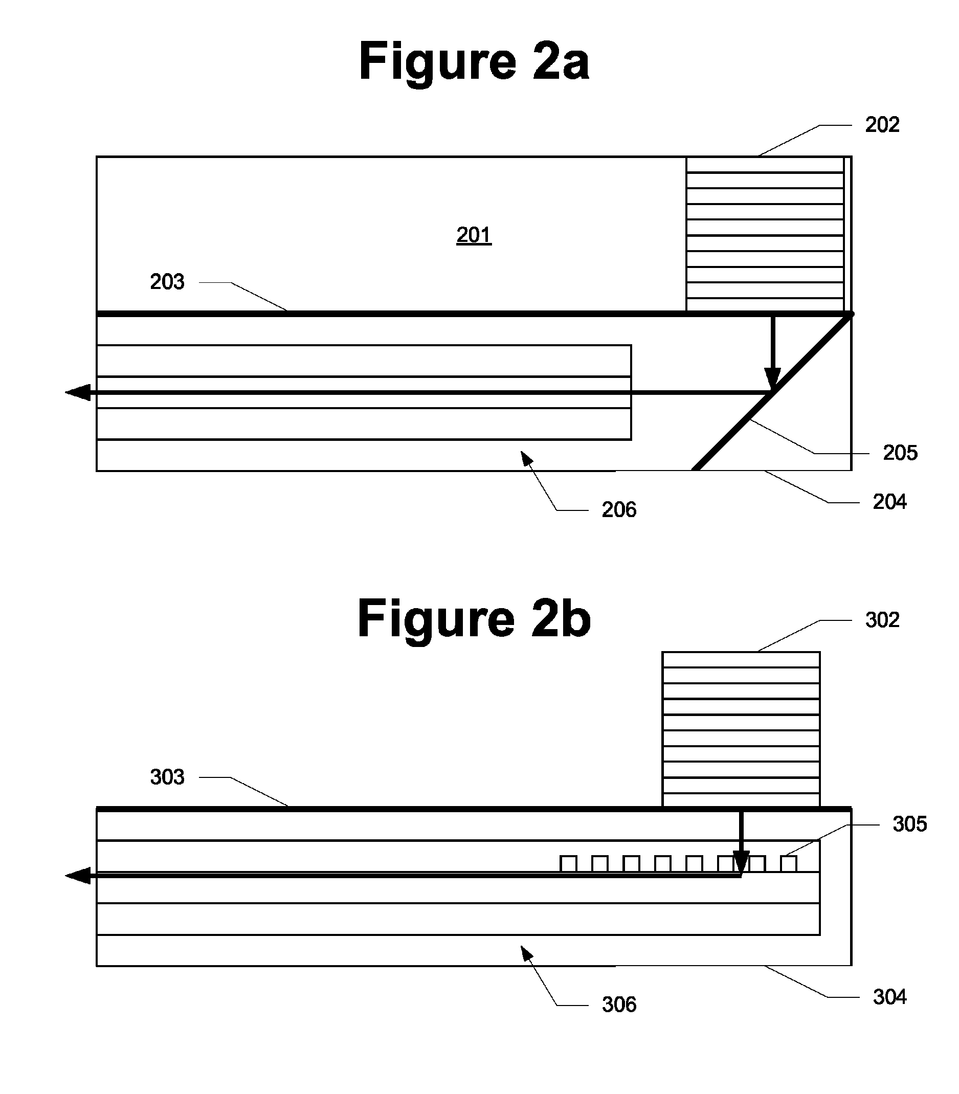
[0016]A vertical cavity surface emitting laser (VCSEL) is a type of semiconductor laser diode in which the laser light is emitted out-of-plane (e.g., from either a top or bottom surface thereof), as opposed to conventional in-plane semiconductor lasers which emit laser light from their edge surfaces (after being cleaved out of the wafer in which they are fabricated). Because VCSELs can emit laser light from the top or bottom surface of the chip in which they are embedded, a wafer containing VCSELs can be aligned with and bonded to a wafer containing magne...


PUM

PropertyMeasurementUnit
temperatureaaaaaaaaaa
refractive indexaaaaaaaaaa
poweraaaaaaaaaa

Abstract

An energy-assisted magnetic recording apparatus comprises a magnetic recording head having an end surface and an interface surface perpendicular to the end surface. The apparatus further comprises a vertical cavity surface emitting laser (VCSEL) bonded to the interface surface and configured to emit laser light through the interface surface and into the magnetic recording head. The magnetic recording head includes one or more light redirecting structures for redirecting the laser light towards the end surface. A method of making an energy-assisted magnetic recording apparatus comprises the steps of aligning a first wafer including a plurality of VCSELs with a second wafer including a plurality of magnetic recording heads, such that an emitting region of each of the plurality of VCSELs is disposed over a light redirecting structure of a corresponding one of the plurality of magnetic recording heads, and bonding the first wafer to the second wafer.

Description

FIELD OF THE INVENTION[0001]The present invention generally relates to energy-assisted magnetic recording (EAMR) and, in particular, relates to the integration of a vertical cavity surface emitting laser (VCSEL) on an EAMR head.BACKGROUND OF THE INVENTION[0002]To increase the areal storage density of a magnetic recording device, the recording layer thereof may be provided with smaller and smaller individual magnetic grains. This reduction in grain size soon reaches a “superparamagnetic limit,” at which point the magnetic grains become thermally unstable and incapable of maintaining their magnetization. The thermal stability of the magnetic grains can be increased by increasing the magnetic anisotropy thereof (e.g., by utilizing materials with higher anisotropic constants). Increasing the magnetic anisotropy of the magnetic grains, however, increases their coercivity and therefore requires a stronger magnetic field to change the magnetic orientation of the grains (e.g., in a write op...

Claims


Application Information

Patent Timeline
Patent Type & Authority Patents(United States)
IPC IPC(8): G11B11/00
CPCG11B5/314G11B5/6088G11B2005/0021Y10T29/49044Y10T29/49048Y10T29/49052Y10T29/49039Y10T29/49041Y10T29/49043
Inventor HU, YUFENGLI, JINSHAN
Owner WESTERN DIGITAL TECH INC
Why Eureka
Try Eureka