
System and method for chemical potential energy production

a technology of chemical potential energy and system, applied in the field of system and method for chemical potential energy production, can solve the problems of low-cost production of potent fuels and difficult tasks

Active Publication Date: 2012-09-18
YEDA RES & DEV CO LTD
View PDF12 Cites 4 Cited by
  • Summary
  • Abstract
  • Description
  • Claims
  • Application Information

AI Technical Summary

Benefits of technology

[0064]In other embodiments, the method comprises exposing the gas molecules to a radiation or an electrons beam, magnetic, or electric field (e.g. fluctuating field at different orientation) to increase the vibration energy of the gas molecules.

Problems solved by technology

The abundant, low-cost production of potent fuels, which can be used in intrinsically clean energy processes, i.e. processes which do not produce and emit greenhouse gases and other pollutants is a challenging task.

Method used


Image

  • System and method for chemical potential energy production
  • System and method for chemical potential energy production
  • System and method for chemical potential energy production

Examples


Embodiment Construction

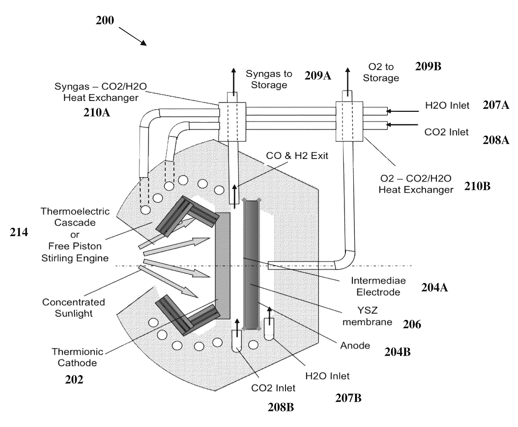
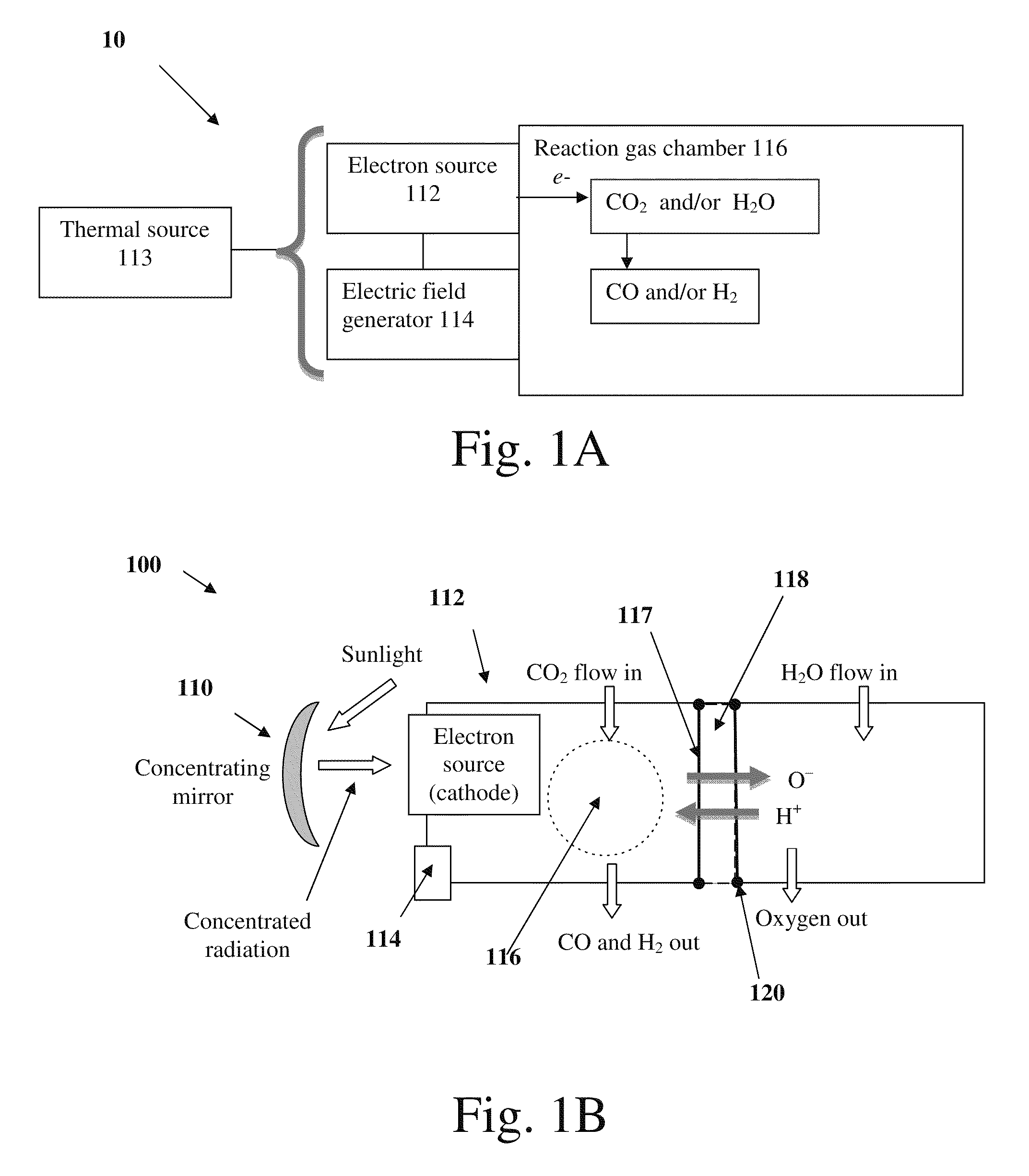
[0073]Reference is made to FIG. 1A representing a schematic block diagram of the main functional elements of the system of the present invention. System 10 comprises an electron source 112 configured and operable to emit electrons, the electron source 112 is exposed to a thermal energy source 113 raising the temperature of the electron source 112; an electric field generator 114 generating an electric field adapted to supply an energy field sufficient to dissociate gas molecules (CO2 and / or H2O), the electric field generator being exposed to thermal energy flux, either from the thermal energy source 113, or from the electron source 112, or both; a main reaction gas chamber 116 configured and operable to cause interaction between the electrons with CO2 and / or H2O; such that the electrons dissociate CO2 and / or H2O to CO and H2 respectively and negative oxygen ions via dissociative electrons attachment (DEA) within the chamber and / or electrolysis.

[0074]The system and method of the pres...


PUM

PropertyMeasurementUnit
temperaturesaaaaaaaaaa

Abstract

The present invention relates to a system comprising a heat source to provide heat at the desired temperature and energy field (e.g. a solar concentrator); an electron source configured and operable to emit electrons; an electric field generator generating an electric field adapted to supply energy sufficient to dissociate gas molecules; and a reaction gas chamber configured and operable to cause interaction between the electrons with the molecules, such that the electrons dissociate the molecules to product compound and ions via dissociative electrons attachment (DEA) within the chamber.

Description

RELATED APPLICATIONS[0001]This application is a Continuation of PCT application Ser. No. PCT / IL2009 / 000743 filed on Jul. 29, 2009 which claims priority to U.S. provisional application Ser. No. 61 / 129,913 filed on Jul. 29, 2008 both of which are incorporated herein by reference in their entirety.FIELD OF THE INVENTION[0002]This invention generally relates to a system and method for chemical potential energy productionREFERENCES[0003]The following references are considered to be pertinent for the purpose of understanding the background of the present invention:[0004]1. Rubin, R., Karni, J. and Yeheskel, J., (2004) “Chemical Kinetics Simulation of High Temperature Hydrocarbons Reforming Using a Solar Reactor,”J. Solar Energy Engineering 126(3), pp. 858-866.[0005]2. Fletcher, E. A., (2001) “Solarthermal Processing: A Review,”J. Solar Energy Engineering 123(2), pp 63-74.[0006]3. Steinfeld, A., (2005) “Solar Thermochemical Production of Hydrogen-a Review,”Solar Energy, 78, pp. 603-615.[00...

Claims


Application Information

Patent Timeline
Patent Type & Authority Patents(United States)
IPC IPC(8): C25B9/08C25B1/10C25B9/19C01B32/40
CPCC01B3/04C01B3/042C01B13/0203C01B13/0207C25B1/003C25B9/08C01B13/0251Y02E60/366C01B2210/0053Y02E60/364Y02E60/36Y02P20/133C01B32/40C25B1/04C25B1/55C25B9/19
Inventor KARNI, JACOBFERDIMAN, GIDONALIOSHIN, YURY
Owner YEDA RES & DEV CO LTD
Learn More