
Axial-geometry micro-discharge detector

a detector and axial geometry technology, applied in the field of detectors, can solve the problems of complex transport of sampled gas from the source, limitations of other detector technologies using atomic emission techniques, and limitations on use,

Inactive Publication Date: 2012-09-25
HERRING CYRUS M
View PDF18 Cites 5 Cited by
  • Summary
  • Abstract
  • Description
  • Claims
  • Application Information

AI Technical Summary

Benefits of technology

"This patent describes a new detector that uses a miniature gas microdischarge to analyze the composition of gas. The detector consists of an optical fiber, inner and outer electrically conductive tubes, and a small space between them where gas flows. The detector emits light that is analyzed by optical sensing equipment to identify the type and concentration of gases in the discharge. The invention has technical effects in providing a compact and efficient gas analysis tool for various applications such as environmental monitoring and industrial process control."

Problems solved by technology

Other detector technologies using atomic emission techniques have limitations on use, such as Atomic Emission Detectors (AED).
The instrument is generally limited to bench-top laboratory applications due to its size and power requirements, and it has the complexity of transporting the sampled gas from the source to the low-pressure plasma region.
These systems suffer from size and power requirements making economic compact analyzers out of reach.
One of these approaches is Laser Induced Breakdown Spectroscopy (LIBS), which needs a relatively expensive laser system for operation.
Spectroscopic detector technologies such as fourier transform infrared spectroscopy (FTIR) have size and costs restrictions, and FTIR cannot detect atomic species nor homonuclear species such as Hg, Cd, Se, Cu, Zn, Pb, Ni, O2, N2, Cl2, etc.

Method used


Image

  • Axial-geometry micro-discharge detector
  • Axial-geometry micro-discharge detector
  • Axial-geometry micro-discharge detector

Examples


Embodiment Construction

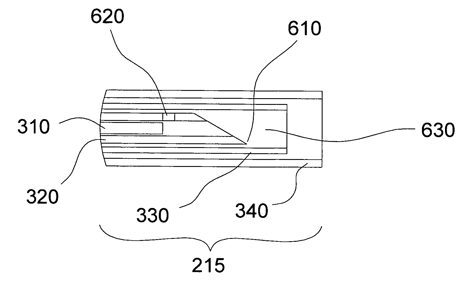
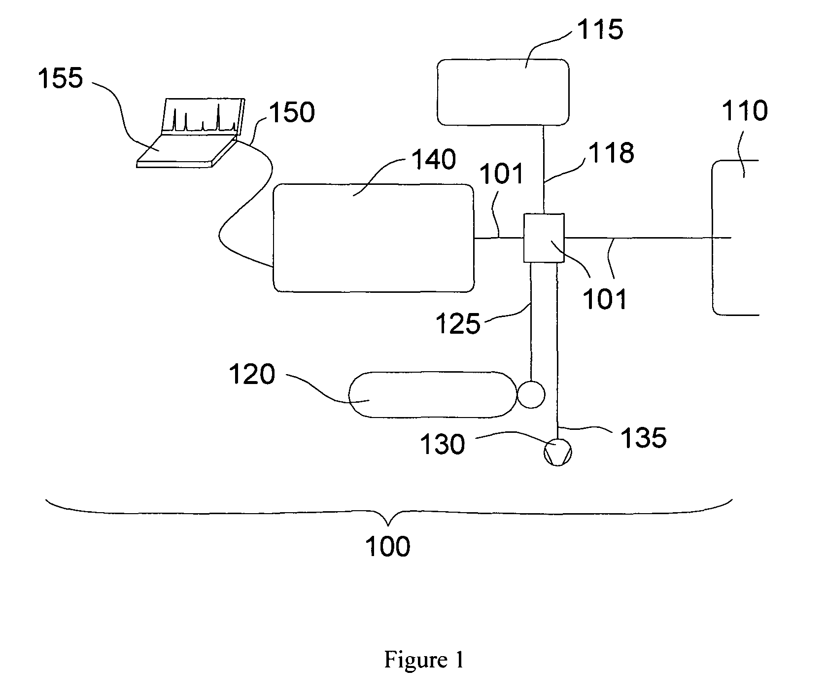
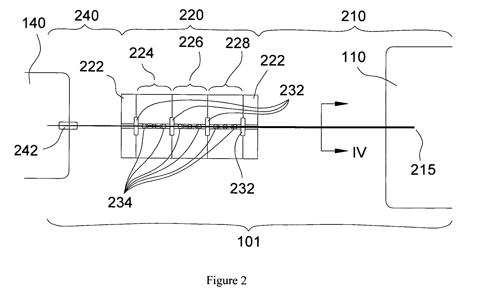
[0030]FIG. 1 illustrates a schematic of a detector system 100. The detector system 100 consists of a detector 101, power supply 115, power cord 118, gas supply 120, gas supply tube 125, vacuum pump 130, vacuum tube 135, optical sensing device 140, communication cord 150, and computer 155. The detection target 110 is any gaseous source in need of monitoring specific properties of the gas.

[0031]The power supply 115 is a small battery powered device, with 2 C-cells providing enough power for twenty-four hours of continuous operation. Alternatively, the power supply 115 is sized and receives the power required to operate the needs of detector system 100. A stabilizing ballast resistor (ranging from 100 k to 10M Ohms) is also included in the electrical circuit. The computer 155 is a laptop. Alternatively, the computer 155 is a more compact integrated electronics included in the detection system enabling analysis in a stand alone portable instrument. As an additional alternative, the comp...


PUM

PropertyMeasurementUnit
pressuresaaaaaaaaaa
temperaturesaaaaaaaaaa
temperatureaaaaaaaaaa

Abstract

A detection device capable of giving atomic and molecular compositions of gases made of concentric tubes and a fiber optic. The body of the detector holds these constituents in their relative positions. A micro-discharge is created between two of the concentric tubes at the tip of the device. The small size of the tubes allows a stable discharge to be achieved. The light from this discharge is delivered from the discharge area to an optical sensing device through the fiber optic. The optical sensing device, along with a computer, analyzes the light to determine the composition of the gas in the discharge. Gas and vacuum are applied through the tubes as needed to aid operation. The detector can be battery powered and used in both hot and toxic environments. Alternatively, a voltmeter can be used to measure impedance across the discharge thus providing another means to determine relative changes in gas composition.

Description

CROSS-REFERENCE TO RELATED APPLICATION[0001]This application claims the benefit of U.S. Provisional Application Ser. No. 60 / 962,771, Jul. 31, 2007.FIELD OF THE INVENTION[0002]This invention pertains to a detector which can identify atomic and molecular components of different gases. More particularly, this invention describes a spectroscopic-based micro-discharge detector used for identification of atomic and molecular compositions of gases and for gas chromatography applications.BACKGROUND OF THE INVENTION[0003]In industrial gas analysis, extractive gas detection and analysis begins with the collection of gas to be analyzed. This often involves bringing the gas from a hostile environment, such as the inside of a smoke stack, to equipment capable of performing an analysis of the gas, which is usually not in the same environment (i.e., the gas detection equipment is outside the smokestack). The gas is carried through tubing, usually ¼″-stainless steel or plastic. Gas temperature diff...

Claims


Application Information

Patent Timeline
Patent Type & Authority Patents(United States)
IPC IPC(8): G01N30/64G01N30/72
CPCG01N30/74G01N30/64G01N21/67G01N30/6095
Inventor HERRING, CYRUS M.
Owner HERRING CYRUS M
Learn More