Nephelometer with concentration-modulated sample flow

a concentration-modulated, sample-flow technology, applied in the direction of instruments, suspensions and porous materials analysis, material analysis, etc., can solve the problems of forming a background noise level and cannot be separated out by light modulation techniques, and achieves a higher signal-to-noise ratio, easy filtering, and high instrument sensitivity results.

a concentration-modulated, sample-flow technology, applied in the direction of instruments, suspensions and porous materials analysis, material analysis, etc., can solve the problems of forming a background noise level and cannot be separated out by light modulation techniques, and achieves a higher signal-to-noise ratio, easy filtering, and high instrument sensitivity results.

US8284398B2Inactive Publication Date: 2012-10-09MET ONE INSTR

Image

  • Nephelometer with concentration-modulated sample flow
  • Nephelometer with concentration-modulated sample flow

Examples


Embodiment Construction

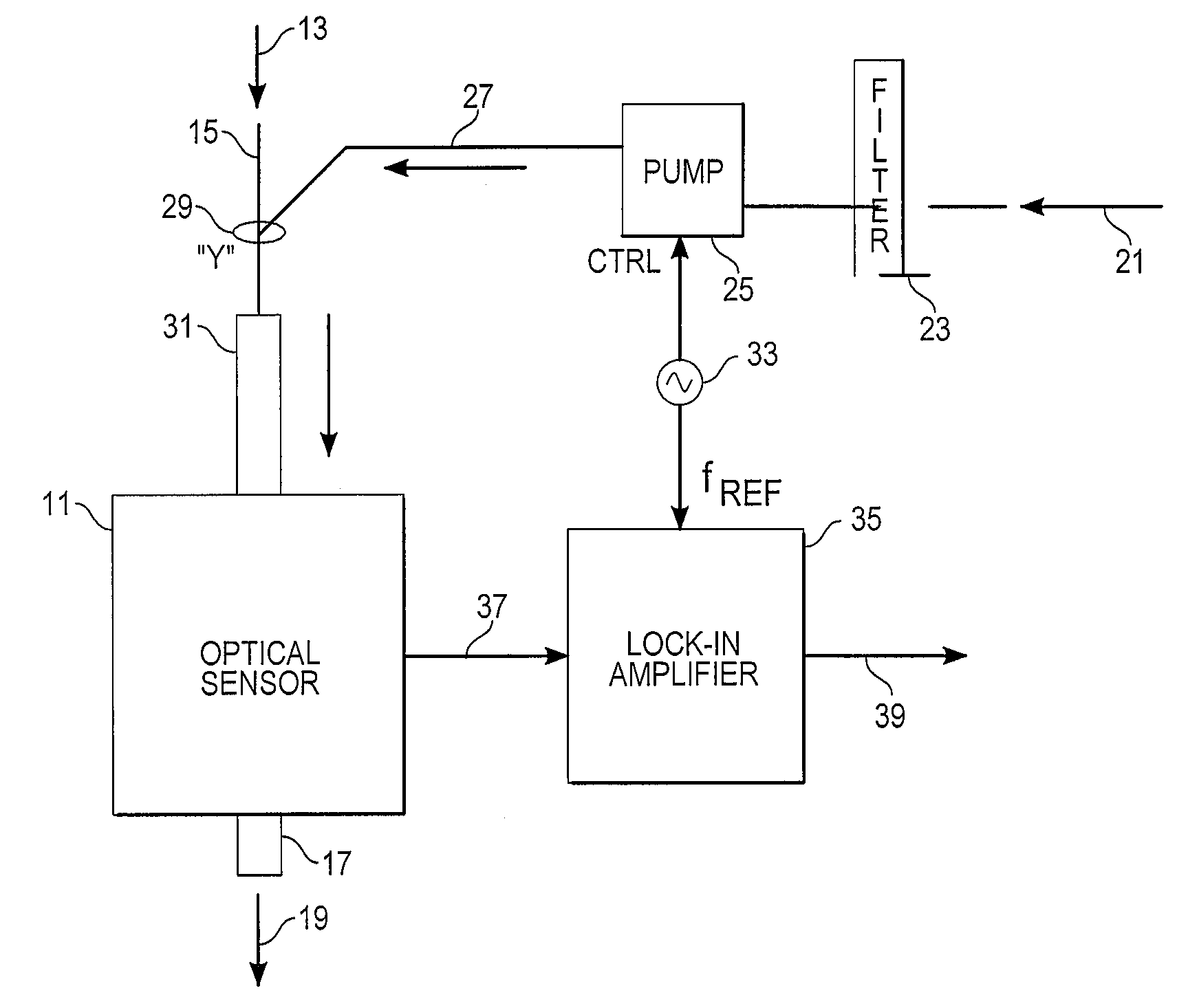
[0010]With reference to FIG. 1, a nephelometer instrument in accord with the present invention includes an optical sensor unit 11, which may be any of the known particle scattering sensors for such instruments, including a light source, such as a diode laser or light-emitting diode (LED), to illuminate a view volume receiving an aerosol sample having particles suspended in a gas carrier, and a light detector positioned to detect light scattered from the illuminated particles in the view volume. The aerosol or particle-laden gas 13 is received through a sample intake 15, flows through the view volume of the optical sensor unit 11, and is then exhausted 19 from the sensor unit's output 17. The particles in the aerosol sample may be solid or liquid and scatter the illuminating light. As in the prior instruments, the light source may provide either constant light output or be intensity modulated at some specified modulation frequency. Intensity modulation of the illumination would gener...


PUM


Abstract

A nephelometer for detecting the concentration of particulates in a sample aerosol is provided with a branched flow path with a sample aerosol input, a clean gas input and an output leading to an optical sensor unit. At least one of the inputs has periodic variable flow so that a concentration-modulated gas stream is supplied to the optical sensor unit. The detector output of the sensor unit is processed in synchrony with the concentration modulation to filter out DC components, such as 1 / f noise and parasitic instrument noise.

Description

TECHNICAL FIELD[0001]The present invention relates to optical measuring and testing of aerosol samples by particle light scattering, as in a nephelometer instrument, and in particular to reducing DC and parasitic instrument background noise or otherwise separating such noise from the particle scatter signal.BACKGROUND ART[0002]Nephelometer instruments for measuring the mass per unit volume of ambient aerosols have historically used a light source, such as a diode laser or light-emitting diode (LED), to illuminate a view volume containing particles suspended in a gas carrier. The amount of detected optical scatter from the illuminated particles in the view volume has then been taken as a measure indicative of the amount (mass) of particulate material in the aerosol. Continuous or near-continuous, near-real-time monitoring of the mass, for example in ambient air, can be accomplished by continuously or near-continuously sampling the ambient by pulling the particle carrier gas into and ...

Claims


Application Information

Patent Timeline
09 Oct 2012
Publication
US8284398B2
IPC
G01J3/46
CPC
G01N15/06; G01N21/53; G01N2015/0693; G01N15/075
Inventors
DEFREEZ, RICHARD K.; POTTER, MICHAEL A.