
Cell management system

a cell management and cell technology, applied in the field of cell management systems, can solve the problems of increasing the chances that another cell will reach its limit, affecting the efficiency of balancing, etc., and achieves the effects of small time, precise measurement, and less efficient balancing

Inactive Publication Date: 2012-10-16
IPS SYST INC
View PDF34 Cites 42 Cited by
  • Summary
  • Abstract
  • Description
  • Claims
  • Application Information

AI Technical Summary

Benefits of technology

"The present invention is about a system and method for balancing individual cells or modules in a battery. The system allows for simultaneous charging or discharging of cells, which can improve battery performance and prevent damage from overcharging or overdischarging. The system can also monitor and control the temperature of cells to prevent overheating or combustion. The invention can be used in various battery and battery cell management systems, extending the life of batteries and ensuring safer and higher performance."

Problems solved by technology

This non-uniformity tends to magnify differences in a cell's State of Charge (SOC) over time when compared to other cells similarly charged and discharged.
While most battery cells (and hence the battery) display some sort of degradation in performance if over- or undercharged, the Li-ion battery has a history of causing fires if overcharged and their cost makes damaging them in a low SOC an event that is to be avoided.
The problem with this strategy is that on occasion, the removal of a cell during discharge causes the other cells to work harder to discharge the required energy, increasing the chances that another cell will reach its limit, which then increases the chance that another cell will reach its limit and so on.
Cascade failure occurs when the battery or battery pack sequentially fails and is removed from the system to the point that the whole system shuts down.
However, as the load (or charge) on a battery increases, the SOC can change materially and non-linearly in very small amounts of time.
Individual readings even over short periods of time can lead to inaccurate measurements and thus less efficient balancing.

Method used


Image

  • Cell management system
  • Cell management system
  • Cell management system

Examples


Embodiment Construction

[0043]The exemplary embodiments of the present invention described below are not intended to be exhaustive or to limit the invention to the precise forms disclosed in the following detailed description. Rather, the embodiments are chosen and described so that others skilled in the art may appreciate and understand the principles and practices of the present invention.

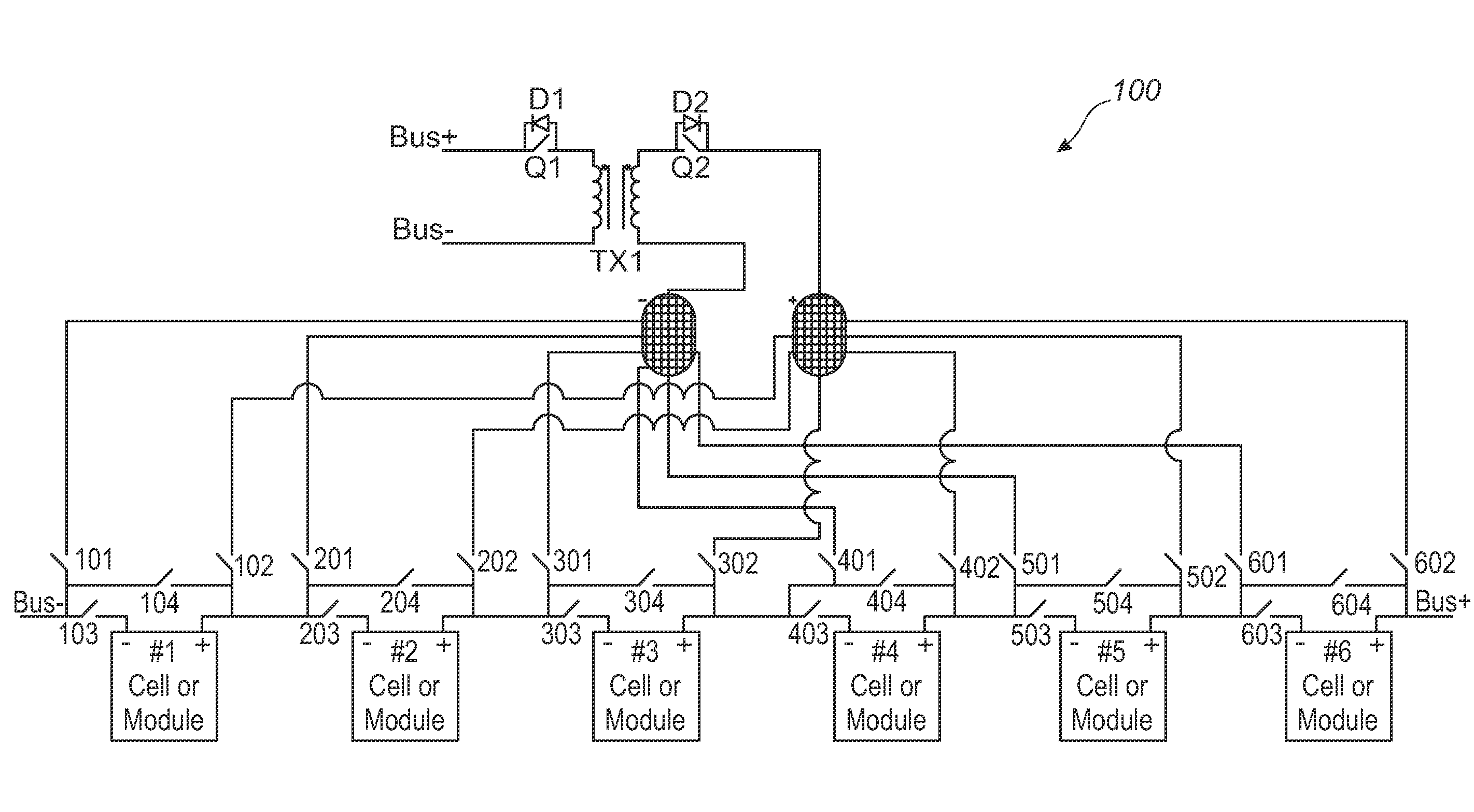
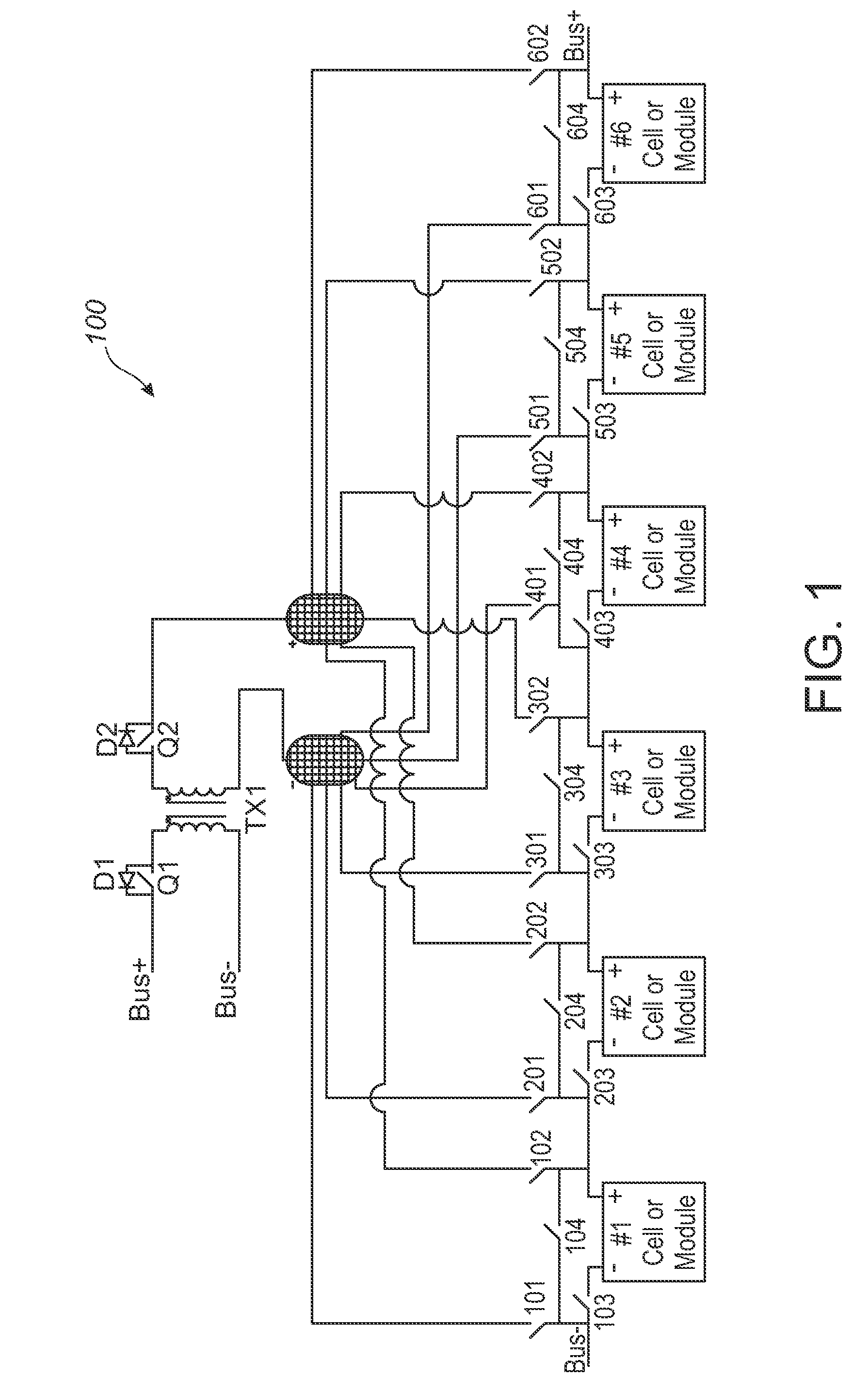
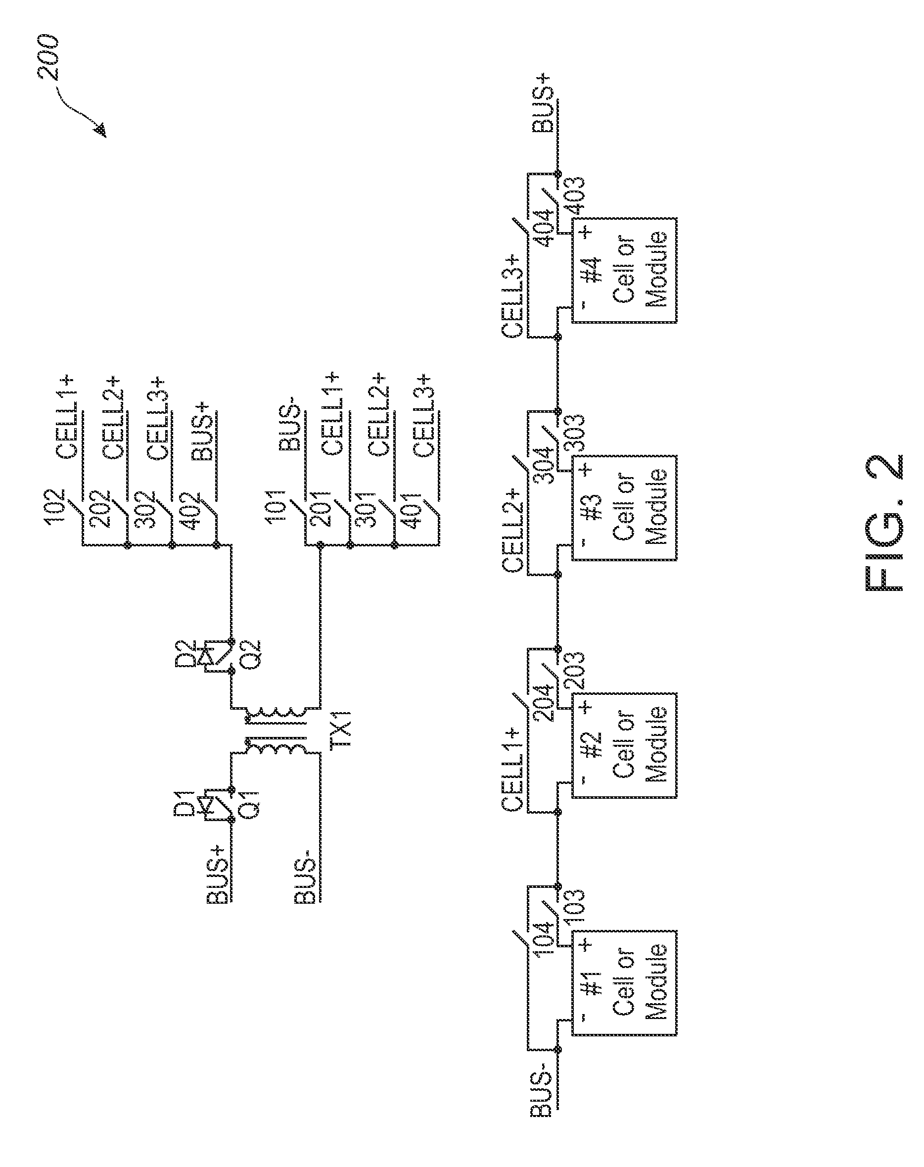
[0044]An example of the value of a cell management system would be in the design of a Lithium-ion (Li-ion) battery. The manufacturing process of Li-ion battery cells leads to variations that correlate to potentially unbalanced cells if unmanaged. Without voltage balancing, the cells in a Li-ion battery will become out of balance, with one or more cells in the series above or below the average cell voltage of the battery. Without a balancing system, as the battery cells are charged and discharged in a series, the difference in voltage grows until such a time that the voltage difference becomes critical and the battery ma...


PUM


Abstract

A cell management system and method for balancing energy across a plurality of cells coupled to a circuit bus. The system can include a transformer, two transformer switches, and for each cell, a first switch pair allowing transfer of energy between the transformer and the cell, and a second switch pair allowing removal or inclusion of the cell in the serial connection of cells. The system can include an energy storage device, a switch pair allowing transfer of energy between the transformer and the storage device, and for each cell, a third switch pair allowing transfer of energy between the storage device and the cell. The system can include cell, bus and storage device sensors and state estimators. The system can include a controller that controls the transformer switches, cell switches, and storage device switches based on the sensor readings and states.

Description

[0001]This application claims priority to U.S. Provisional Patent Application Ser. No. 61 / 144,596, filed Jan. 14, 2009 entitled “Cell Management System,” the disclosure of which is expressly incorporated herein by reference.BACKGROUND AND SUMMARY[0002]The present invention generally relates to an apparatus and methodology for allowing a single battery cell or module to be charged or discharged in parallel within a series circuit, so that the cells or modules can be balanced either during charging, discharge, or at rest (i.e. not being charged or discharged via an outside source.).[0003]There is a growing need for cell balancing because there are inconsistencies in the construction and materials of every cell that while small, can have a material impact on the cell's charge and discharge characteristics. This non-uniformity tends to magnify differences in a cell's State of Charge (SOC) over time when compared to other cells similarly charged and discharged. While balancing cell SOC i...

Claims


Application Information

Patent Timeline
Patent Type & Authority Patents(United States)
IPC IPC(8): H02J7/00H02J7/16
CPCH02J7/0016
Inventor KRAMER, QUENTIN WAYNEHINTZ, ANDREW S.GALYEN, ROBERT L.
Owner IPS SYST INC
Learn More