Microelectromechanical resonant structure having improved electrical characteristics

a micro-electromechanical and electrical characteristics technology, applied in the direction of electrical apparatus, device details, push-pulse automatic control, etc., can solve the problems of counterbalancing advantages and inability to regulate the operating frequency of devices, and achieve the reduction of energy consumption, motion resistance, and motion resistance

Active Publication Date: 2012-10-16
STMICROELECTRONICS SRL
View PDF10 Cites 9 Cited by
  • Summary
  • Abstract
  • Description
  • Claims
  • Application Information

AI Technical Summary

Benefits of technology

[0014]The present applicant has found that a reduction of the motional resistance would be certainly desirable in so far as it would enable reduction of the energy consumption of the ASIC associated to the micromechanical resonant structure, avoiding in particular the introduction of charge pumps for reaching the high values of biasing voltage. In addition, the reduction of the motional resistance would enable more effective exploitation of the biasing potential for the tunability of the device, both for correction of the shifts of the native frequency (which is intrinsically variable on account of the spread of the photolithographic process) and for the correction of the frequency shifts due to temperature variations.
[0015]The present disclosure provides a MEMS resonant structure having improved mechanical and electrical characteristics, in particular as regards the consumption level and the possibility of regulating the resonance frequency.

Problems solved by technology

However, it has been shown that it is impossible to regulate the operating frequency of the device (to achieve the so-called “tunability”), and hence also to correct the shifts in the same frequency due to the spread of the technological process and to the temperature shifts.
However, this advantage is counterbalanced by the difficulty of obtaining in this case an efficient capacitive coupling, and hence a low equivalent resistance (the so-called “motional resistance”) of the mechanical structure.
This drawback is due chiefly to technological limits (linked to the photolithographic technologies used for the definition of the mobile mass) in providing gaps that can be controlled and are sufficiently small (less than a micron) between the mobile mass and the fixed electrodes over the entire wafer, and a facing area that is sufficiently large between the same elements.

Method used


Image

  • Microelectromechanical resonant structure having improved electrical characteristics
  • Microelectromechanical resonant structure having improved electrical characteristics
  • Microelectromechanical resonant structure having improved electrical characteristics

Examples


Embodiment Construction

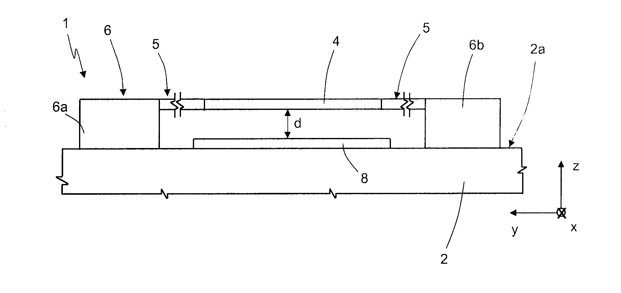
[0024]As will be clarified in detail in what follows, one aspect of the present disclosure envisages providing a micromechanical resonant structure of a vertical type, in which the mobile mass is able to oscillate in resonance in a direction transverse to the top surface of the substrate, instead of parallel to the same substrate. The mobile mass is capacitively coupled, in parallel-plate configuration, to at least one fixed electrode set on the substrate in such a way that the characteristic gap of the resonant structure is to be determined by the height of the layer of air between the mobile mass and the fixed electrode (the thickness of this vertical gap can thus be easily regulated and reduced in value, as described hereinafter, by means of etching and removal of a region of sacrificial material).

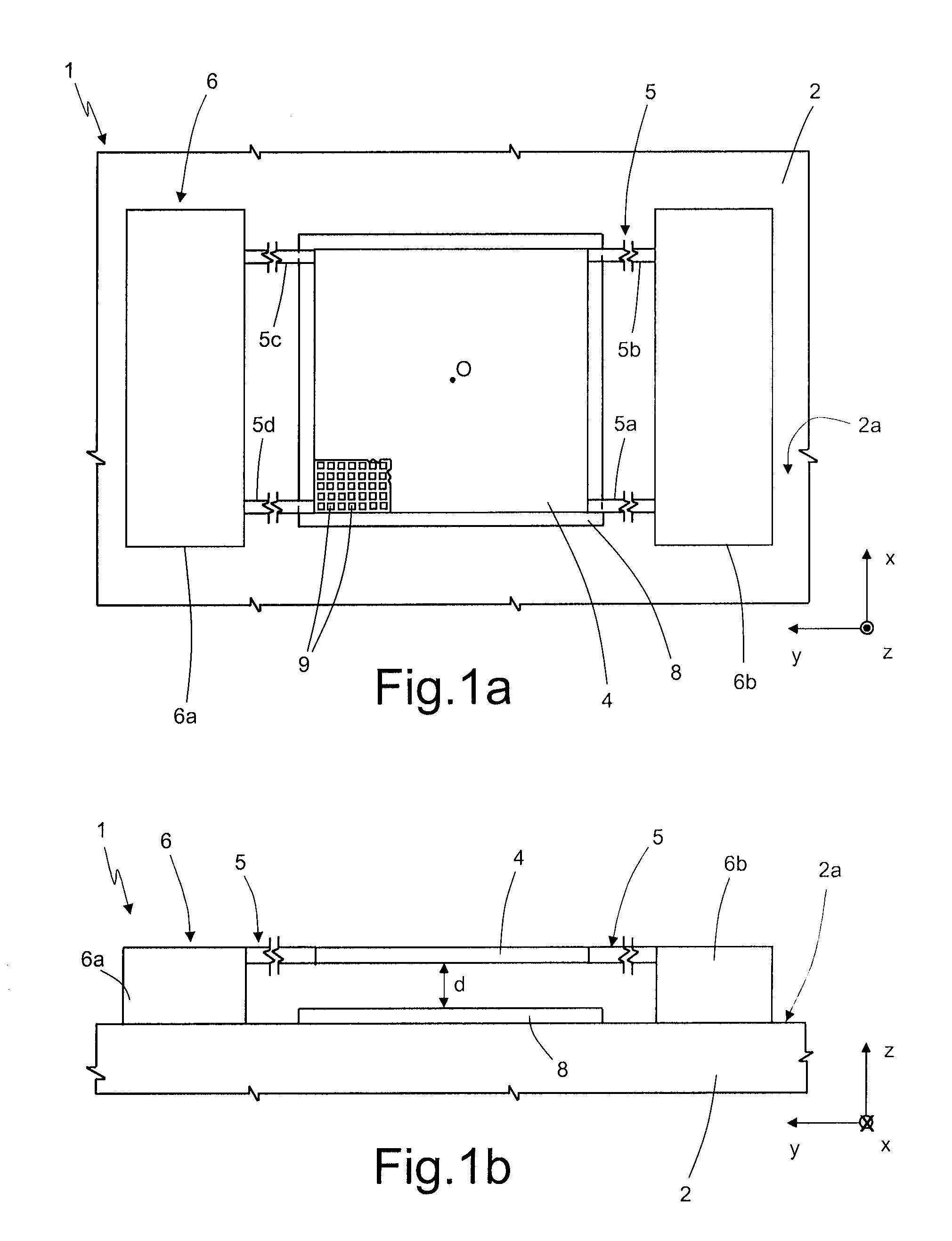
[0025]As illustrated schematically in FIGS. 1a and 1b, a MEMS resonant structure, designated as a whole by 1, has a substrate 2 of semiconductor material, in particular silicon, having ...


PUM


Abstract

The present disclosure is directed to a MEMS resonant structure, provided with a substrate of semiconductor material; a mobile mass suspended above the substrate and anchored to the substrate by constraint elements to be free to oscillate at a resonance frequency; and a fixed-electrode structure capacitively coupled to the mobile mass to form a capacitor with a capacitance that varies as a function of the oscillation of the mobile mass; the fixed-electrode structure arranged on a top surface of the substrate, and the constraint elements being configured in such a way that the mobile mass oscillates, in use, in a vertical direction, transverse to the top surface of the substrate, keeping substantially parallel to the top surface.

Description

BACKGROUND[0001]1. Technical Field[0002]The present disclosure relates to a resonant microelectromechanical structure (MEMS) with improved electrical characteristics, in particular for real-time-clock (RTC) applications, to which the following treatment will make reference without this implying any loss of generality.[0003]2. Description of the Related Art[0004]As is known, RTC devices are commonly used operating as a clock in electronic apparatuses, whether portable or not, such as for example cell phones, video cameras or photographic cameras, automotive apparatuses, electrical household appliances, data-collection terminals, smart-card readers, etc., in order to count the passage of real time (in terms of years, months, days, hours, minutes, and seconds), even when the corresponding electronic apparatuses are turned off. An RTC device generally comprises for the purpose: an oscillator circuit provided with an appropriate resonant structure designed to generate an operating freque...

Claims


Application Information

Patent Timeline
Patent Type & Authority Patents(United States)
IPC IPC(8): H03B5/30H01L41/02
CPCH03H9/02259H03H9/02338H03H9/02409H03H9/02433H03H9/2436H03H2009/02511H03H2009/2442
Inventor POMARICO, ANNAFLORA, PASQUALEMOREA, ANNARITAROSELLI, GIUDITTA
Owner STMICROELECTRONICS SRL
Why Eureka
Try Eureka