Electrophotographic photoreceptor, method of manufacturing electrophotographic photoreceptor, image forming apparatus, and process cartridge

a photoreceptor and electrophotography technology, applied in the field of electrophotographic photoreceptors, can solve the problems of unsatisfactory application of solid lubricants to photoreceptor surfaces, difficult removal of polymerization toner particles, and insufficient application of external additives, etc., to achieve good receptivity and good receptivity

Active Publication Date: 2012-10-23
RICOH KK
View PDF86 Cites 6 Cited by
  • Summary
  • Abstract
  • Description
  • Claims
  • Application Information

AI Technical Summary

Benefits of technology

[0046]Accordingly, exemplary embodiments of the present invention provide an electrophotographic photoreceptor having good receptivity to solid lubricants, a method of manufacturing such an electrophotographic photoreceptor having good receptivity to solid lubricants, and an image forming apparatus and a process cartridge having a long lifespan.

Problems solved by technology

At the same time, disadvantageously, polymerization toner particles are difficult to be removed when remaining on a photoreceptor.
As a result, the external additives may form undesired films thereof on the photoreceptor.
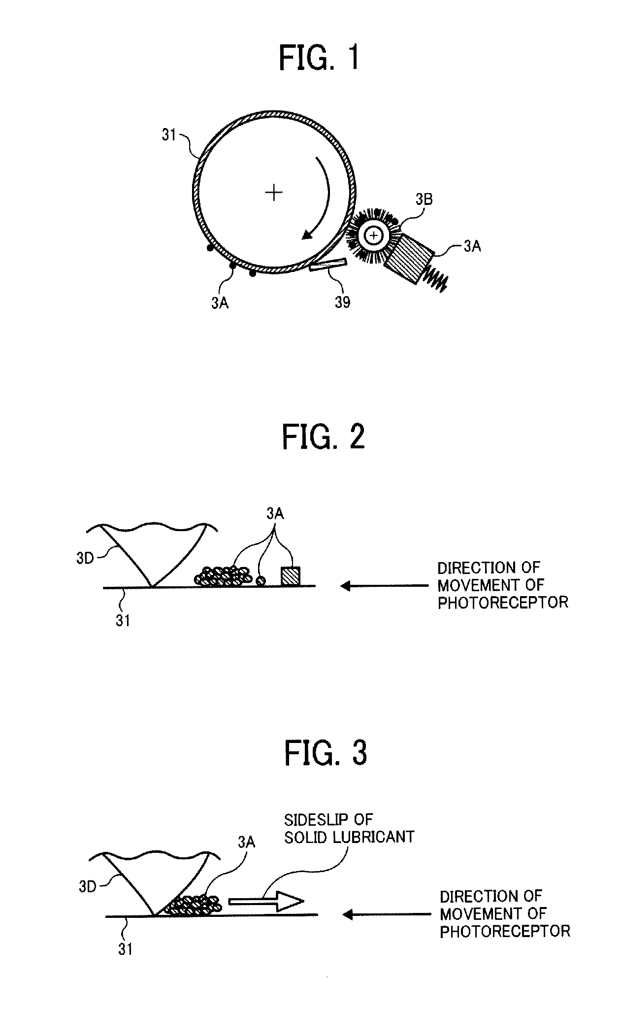
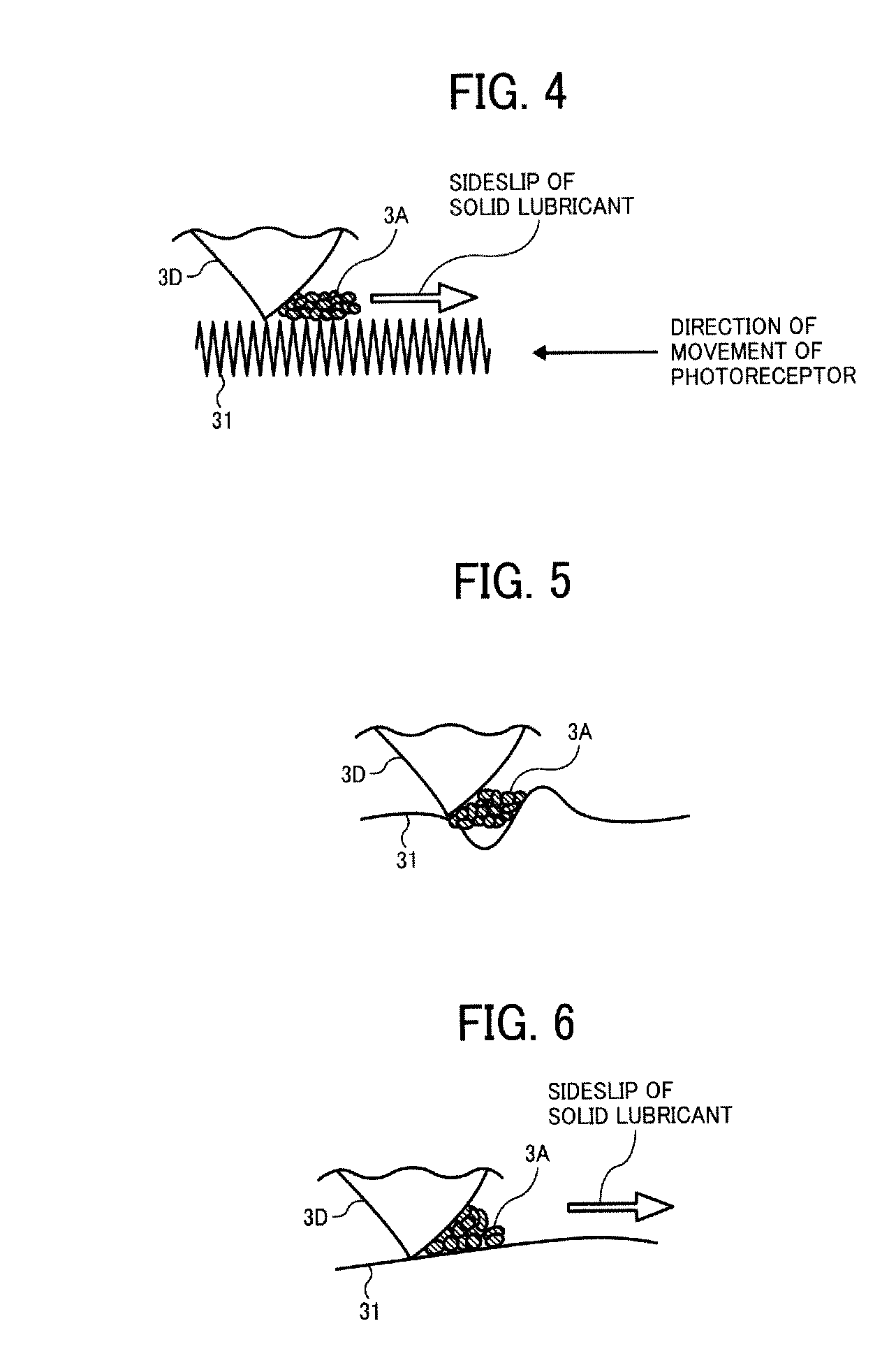
However, a solid lubricant (e.g., zinc stearate) may not be sufficiently applied to a surface of a photoreceptor when the surface is relatively smooth.
Therefore, receptivity of the surface to zinc stearate may not be improved only by controlling the Rz value.
However, these parameters are not satisfactory to evaluate surface roughness of photoreceptors, and various proposals have been made as follows.
Further, disadvantageously, it is not clearly determined from the results of Fourier transform where the variation occurred.
However, none of the above-described methods of evaluating surface roughness is sufficient to evaluate cleanability (removability) of small-size toners and polymerization (spherical) toners from photoreceptor.
However, it requires skill to evaluate surface roughness from the chart.
Namely, any of the parameters (Ra, Rmax, Rz, etc.) does not sufficiently represent cleanability (removability) of small-size toners and polymerization (spherical) toners from photoreceptor.
Since alumina particles are difficult to be uniformly dispersed in a coating material, it requires a special technique to form a uniform coating layer.
Such a photoreceptor does not always sufficiently hold a solid lubricant hereon because of having too large convexities and concavities on the surface thereof.
However, silicon-containing particles do not always provide the resultant photoreceptor with high receptivity to solid lubricants, as seen in Example 2 of JP-A 2005-99688.
This is because the surface of the photoreceptor has too large convexities and concavities to hold solid lubricants.
However, the hydrophobized inorganic grain may not prevent adhesion of corona products while preventing adhesion of water, thereby causing image blurring.
However, any technique to improve the receptivity of a highly-durable photoreceptor having a cross-linked resin surface layer has not been proposed so far.
On the other hand, disadvantageously, such a surface layer has a low receptivity to solid lubricants and therefore cleanability (removability) of polymerization toners is poor.
As a result, highly-durable photoreceptors having a surface layer cannot be practically used in combination with polymerization toners under the current situation.

Method used


Image

  • Electrophotographic photoreceptor, method of manufacturing electrophotographic photoreceptor, image forming apparatus, and process cartridge
  • Electrophotographic photoreceptor, method of manufacturing electrophotographic photoreceptor, image forming apparatus, and process cartridge
  • Electrophotographic photoreceptor, method of manufacturing electrophotographic photoreceptor, image forming apparatus, and process cartridge

Examples


example 1

[0286]On each of an aluminum cylinder having a thickness of 0.8 mm, a length of 340 mm, and an outer diameter of 40 mm, and another aluminum cylinder having a thickness of 0.8 mm, a length of 340 mm, and an outer diameter of 30 mm, a undercoat layer coating liquid, a charge generation layer coating liquid, and a charge transport layer coating liquid are sequentially coated and dried in this order. Thus, an undercoat layer, a charge generation layer, and a charge transport layer having a thickness of 3.5 μm, 0.2 μm, and 24 μm, respectively, are formed on each of the aluminum cylinders.

[0287]Further, a cross-linked resin surface layer coating liquid is spray-coated on the aluminum cylinders having the undercoat layer, the charge generation layer, and the charge transport layer thereon, followed by drying for 10 minutes. The aluminum cylinders are put 120 mm away from a UV curing lamp so that the cross-linked resin surface layer coating liquid is subjected to UV curing while rotating. ...

example 2

[0293]The procedure in Example 1 is repeated except for changing the amount of the cross-Linkable silicone oil material to 0.75 parts.

example 3

[0294]The procedure in Example 1 is repeated except for changing the amount of the non-cross-linkable silicone oil material to 0.45 parts.


PUM

PropertyMeasurementUnit
lengthaaaaaaaaaa
surface roughnessaaaaaaaaaa
lengthaaaaaaaaaa

Abstract

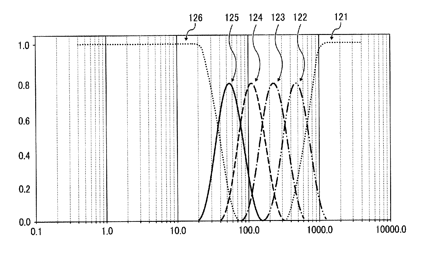
An electrophotographic photoreceptor including a conductive substrate, a photosensitive layer, and a surface layer, which satisfies the following inequations:0.005<WRa(LMH)<0.03  (i)0.010<WRa(LHH)<0.03  (ii)0.005<WRa(LML)<0.20  (iii)WRa(LLH)>WRa(LMH)  (iv)WRa(LLH)>WRa(LHH)  (v)wherein WRa (μm) represents a center-line average roughness of frequency components LHH, LHL, LMH, LML, LLH, and LLL that are obtained by subjecting a one-dimensional data array of a surface profile of the electrophotographic photoreceptor to wavelet transformation multiresolution analysis so as to be separated into 6 frequency components; thinning a one-dimensional data array of the lowest frequency component so that the number of data array is reduced to 1 / 40; and subjecting the thinned one-dimensional data array to wavelet transformation multiresolution analysis so as to be separated into the 6 frequency components LHH, LHL, LMH, LML, LLH, and LLL.

Description

CROSS-REFERENCE TO RELATED APPLICATIONS[0001]This document claims priority from and contains subject matter related to Japanese Patent Applications Nos. 2009-061268 and 2010-046096, filed on Mar. 13, 2009 and Mar. 3, 2010, respectively, the entire contents of each of which are hereby incorporated herein by reference.BACKGROUND OF THE INVENTION[0002]1. Field of the Invention[0003]The present invention relates to an electrophotographic photoreceptor for use in copiers, facsimile machines, laser printers, and direct digital platemakers. In addition, the present invention also relates to a method of manufacturing electrophotographic photoreceptor, and an image forming apparatus and a process cartridge using the electrophotographic photoreceptor.[0004]2. Discussion of the Related Art[0005]Recently, the mainstream of electrophotographic photoreceptor (hereinafter simply “photoreceptor”) has switched from inorganic photoreceptor that uses inorganic materials such as selenium, zinc oxide, a...

Claims


Application Information

Patent Timeline
Patent Type & Authority Patents(United States)
IPC IPC(8): G03G5/147
CPCG03G5/047G03G5/0578G03G5/0592G03G5/0614G03G5/071G03G5/14769G03G5/14773G03G5/14786G03G5/14791G03G5/14795G03G5/076G03G2215/00957G03G5/072G03G5/0732
Inventor FUJIWARA, YUKIOKAMI, HIDETOSHIEGAWA, KAZUHIRONOHSHO, SHINJIYOSHIHARA, MAYUMIMATSUMOTO, MIHOKOYAMAMOTO, KOHSUKE
Owner RICOH KK
Why Eureka
Try Eureka