
Method for pixel shift calculation in digital subtraction angiography and X-ray diagnostic imaging system for generating images in digital subtraction angiography

a diagnostic imaging system and pixel shift technology, applied in image enhancement, instruments, recognition of medical/anatomical patterns, etc., can solve the problems of unwanted flicker, time-consuming background process sampling, and certain latency

Inactive Publication Date: 2012-10-30
SIEMENS HEALTHCARE GMBH
View PDF8 Cites 16 Cited by
  • Summary
  • Abstract
  • Description
  • Claims
  • Application Information

AI Technical Summary

Benefits of technology

[0011]That one of the possible shift vectors which has the highest scoring is then chosen as an elected shift vector, i.e. which is a maximum. It may occur, however, that there are different elected shift vectors with corresponding maximums in the course of time. Therefore, in order to check whether such a maximum has a high quality, the likelihood representing a quality value of this maximum is calculated. Then, a modified shift vector depending on the elected shift vector and the likelihood p is calculated. Thereafter the mask image frame is shifted with respect to the respective live image frame by the modified shift vector. Then, the shifted mask image frame is subtracted from the respective live image frame and the result is displayed on a screen. Due to the modification of the shift vector depending on the likelihood p, the quality of the displayed image is improved and flickering is reduced or even completely avoided.
[0014]According to an advantageous embodiment of the invention, it is the mask image frame which is contrast-enhanced. In this way, the levels of contrast agent to which the patient is exposed may be minimized.
[0018]Testing of the method according the invention showed that very good results may be obtained when the shifting of the mask image frame is made dependent on a certain threshold value T1 of the likelihood p. This threshold value T1 is preferably 0.35.
[0024]This means that, if p is below the threshold value T1, then the application of the elected shift vector is restricted or modified by normalizing the new shift vector to be within a given maximum distance t from the previously applied shift vector. This means in other words that the modified current optimum is obtained by moving the old optimum in the direction of the current optimum, but only by a factor t. In this manner, a sub-pixel shift is possible also in the invention, which provides for reliability and accuracy of the calculation of the new shift vector. This may be particular important in cases where the scanning is so coarse or rough that the real maximum is missed since it is not located at a position which may be reached with shift vector having integer-number components.
[0035]One preferred alternative is to introduce a distinction of cases with respect to the parameter k. In case the likelihood is above a threshold value (which is preferably around 0.35), k is chosen to be 3. In case the likelihood p is on or below the threshold value T2, k is chosen to be 6. This choice has the effect that for a “good” maximum, i.e. having a likelihood p above the threshold value T2, a third of the elected shift vector for the current live image frame is used for calculation of the modified shift vector, whereas two thirds of the elected shift vector for the previous live image frame are used therefor. In contrast thereto, in cases of a “bad” maximum, only one sixth of the elected shift vector for the current live image frame is used for calculation of the current modified shift vector whereas five sixth of the elected shift vector for the previous live image frame are used therefor. This means that the transitions occur very smoothly and that in other words no flicker occurs.

Problems solved by technology

This sampling in the background process is time-consuming and is, therefore, not real-time and causes a certain latency.
These calculated shift vectors are applied without regard to the fact whether or not these shift vectors are accurate may result in unwanted flicker.

Method used


Image

  • Method for pixel shift calculation in digital subtraction angiography and X-ray diagnostic imaging system for generating images in digital subtraction angiography
  • Method for pixel shift calculation in digital subtraction angiography and X-ray diagnostic imaging system for generating images in digital subtraction angiography
  • Method for pixel shift calculation in digital subtraction angiography and X-ray diagnostic imaging system for generating images in digital subtraction angiography

Examples


Embodiment Construction

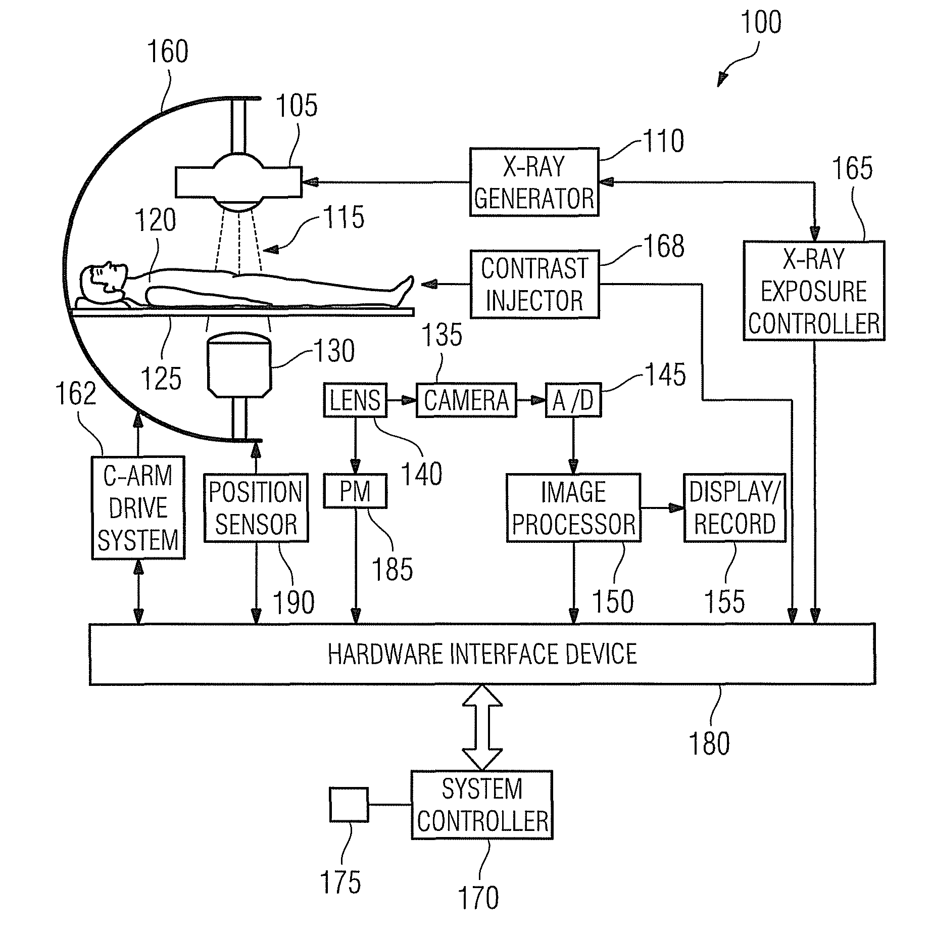
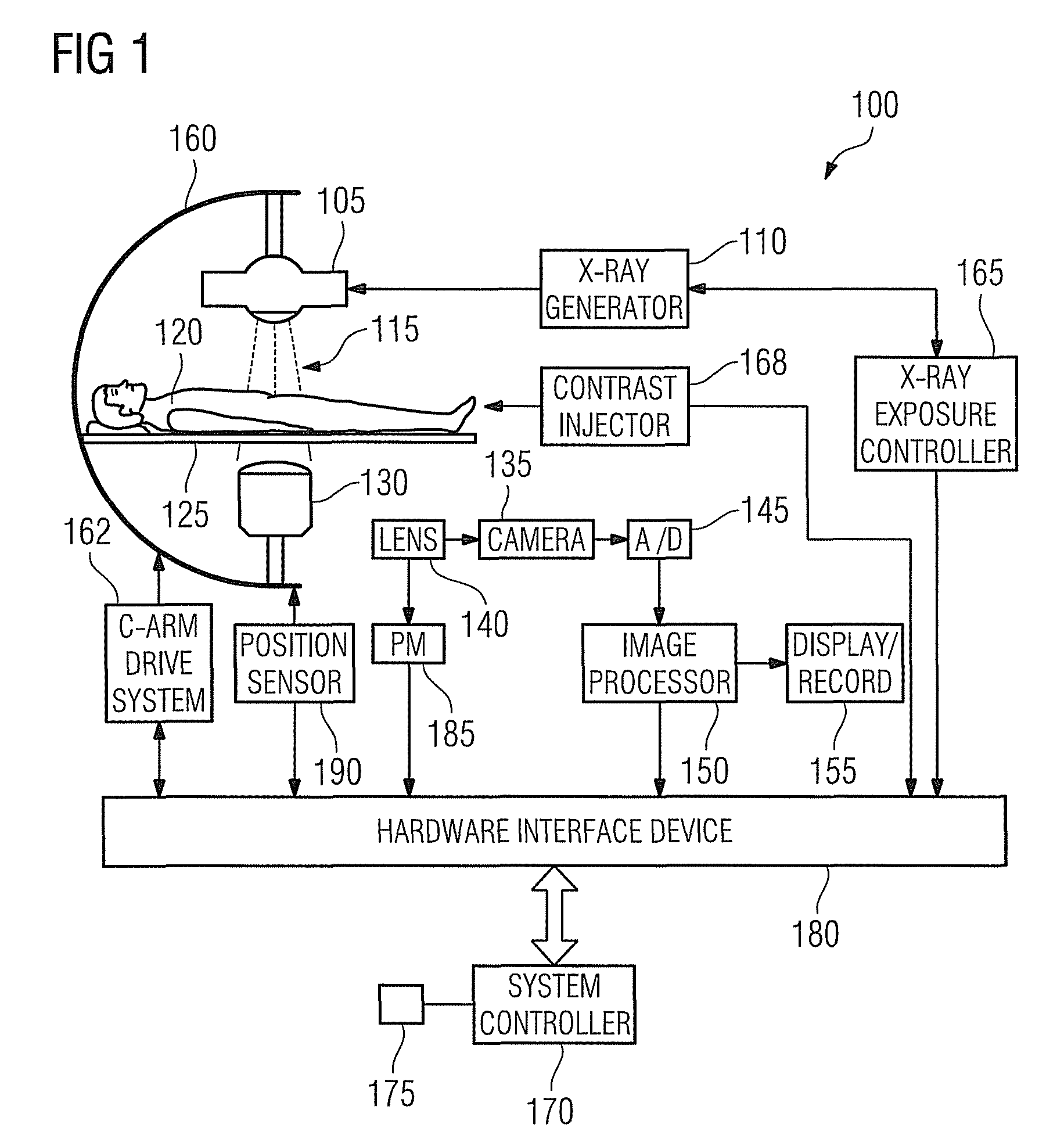
[0047]Reference will now be made in detail to exemplary embodiments of the present invention, examples of which are illustrated in the accompanying drawings, wherein like reference numerals refer to like elements throughout. The terms “process” and “method” are generally used to refer to a series of operations performed by a processor, be it a central processing unit of an X-ray system for live fluoro roadmapping, or a secondary processing unit of such a system. Useful machines for performing exemplary operations of the present invention include the AXIOM family of X-ray diagnostic imaging systems and products, by Siemens Medical Systems. The inventive method or process, however, is not limited to implementation on Siemens' X-ray diagnostic imaging systems, but may be implemented in any known or future X-ray system arranged for conducting real-time X-ray subtraction imaging, including live fluoroscopic procedures.

[0048]FIG. 1 depicts an X-ray diagnostic imaging system 100 for live f...


PUM


Abstract

An X-ray diagnostic imaging system for generating images in digital subtraction angiography is proposed. A mask image frame of a patient and a series of live image frames of the patient acquired in the same imaging position of the mask frame acquisition are accessed. One of the mask and the live image frames is contrast-enhanced. Possible shift vectors in a region of interest are assumed being a difference vector between the mask and a respective live image frame and a scoring is calculated. Possible shift vector with the highest scoring is chosen as an elected shift vector. A likelihood representing a quality value of the elected shift vector is calculated. The mask image frame is shifted with respect to the respective live image frame by a modified shift vector depending on the likelihood. The shifted mask image frame is subtracted from the respective live image frame and is displayed.

Description

FIELD OF THE INVENTION[0001]The present invention relates to subtraction angiography, and more particularly relates to an X-ray diagnostic imaging system and method for correcting for motion between acquired frames in angiographic roadmapping procedures.BACKGROUND OF THE INVENTION[0002]Angiography refers generally to the capture and representation of blood vessels or vasculature of the human body by means of X-ray imaging, i.e., X-ray vascular imaging. X-ray diagnostic imaging systems may be used for angiographic imaging procedures such as digital subtraction angiography (DSA), and live fluoroscopic roadmapping. Digital subtraction angiography or DSA is an imaging method used for visualizing blood vessels inside a patient's body that includes injecting a contrast medium bolus that is substantially opaque to X-rays into the blood vessels or vasculature under study as images are acquired by the X-ray diagnostic imaging system. Prior to acquisition of the contrast image, a mask image w...

Claims


Application Information

Patent Timeline
IPC IPC(8): H01L27/00
CPCG06T5/50G06T7/20G06K2209/05G06T2207/10121G06T2207/30101G06T2207/20224G06T7/0016G06V2201/03
Inventor VOGT, FLORIANBAUMGART, JOHN
Owner SIEMENS HEALTHCARE GMBH
Learn More