Power converter utilizing a RC circuit to conduct during the rising edge of the transformer voltage

a transformer voltage and rc circuit technology, applied in the direction of electric variable regulation, process and machine control, instruments, etc., can solve the problems of high ripple, affecting the accuracy of the measured voltage, and it is difficult to match the requirement for high dynamic performance with high accuracy, so as to increase the input voltage range

Active Publication Date: 2012-10-30
TELEFON AB LM ERICSSON (PUBL)
View PDF17 Cites 4 Cited by
  • Summary
  • Abstract
  • Description
  • Claims
  • Application Information

AI Technical Summary

Benefits of technology

[0011]The concept of the invention is a solution much like the peak rectification scheme described above, but with the addition that the information storage device, the capacitor, can be both charged and discharged every switching cycle. This is achieved by enabling the discharge of the capacitor through a device, such as a MOSFET, that is capable of bidirectional energy transfer. This drastically reduces ripple on the mirrored voltage and also increases the dynamic performance when the storage device is to be discharged.
[0012]The main advantages with the invention are that it creates a highly accurate, both statically and dynamically mirrored signal of the primary voltage using an existing system and only a few low cost components.
[0018]A Zener diode may be arranged between the gate and the source of the second and / or the third transistor to limit the voltage across the respective transistor. This will increase the input voltage range that can be handled by the respective transistor and therefore by the converter.

Problems solved by technology

One problem with this secondary side control is that the control circuit, now placed on the secondary side, has to be biased from the primary side.
This causes a trade-off between high dynamic performance, which causes a high ripple due to a large discharge off the capacitor every cycle, and accuracy, which requires the capacitor to be discharged only slightly for every cycle.
The drawback of the solution using peak rectification above is that it is hard to match the requirement for high dynamic performance with high accuracy.
The forward voltage drop of the rectifying device will also affect the accuracy of the measured voltage.
Another more costly method is to use linear optocouplers.
One drawback with the optocoupler approach is that one extra component crossing the insulation barrier is required.
Also, such a solution is relatively expensive and will also have problem with ageing.
This is a simple inexpensive solution; however, it introduces an error, which means that it may not be sufficiently exact in all fields of applications.

Method used


Image

  • Power converter utilizing a RC circuit to conduct during the rising edge of the transformer voltage
  • Power converter utilizing a RC circuit to conduct during the rising edge of the transformer voltage
  • Power converter utilizing a RC circuit to conduct during the rising edge of the transformer voltage

Examples


Embodiment Construction

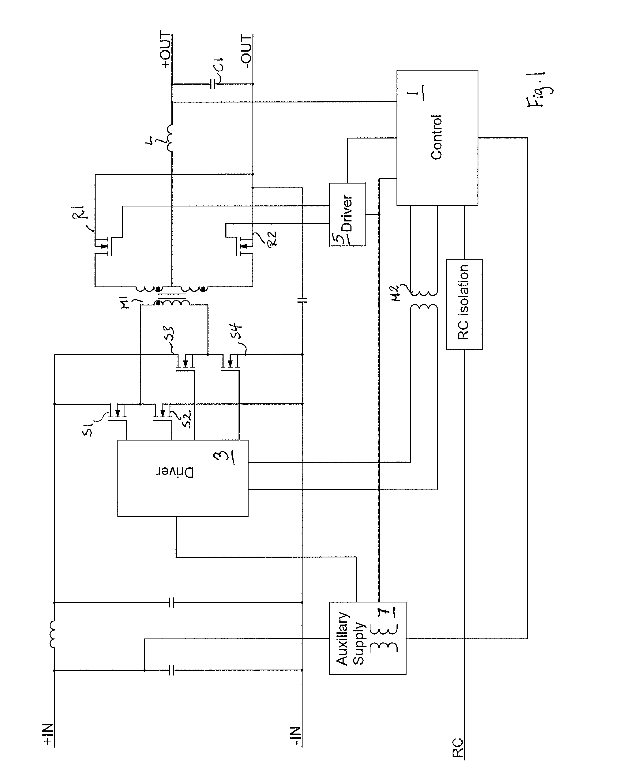
[0027]FIG. 1 illustrates a power converter controlled by a control circuit on the secondary side. The power converter comprises a main transformer M1 controlled by a number of switch elements S1, S2, S3, S4 on the primary side. The switch elements are controlled by a primary side driver unit 3. On the secondary side two rectifying elements R1, R2 are connected to opposite ends of the secondary winding. The rectifying elements R1, R2 are controlled by a secondary side driver unit 5. The output voltage is extracted between a centre tap of the secondary winding and one of the rectification elements using an inductor L1 and a capacitor C1 in a way common in the art.

[0028]The control unit 1 is connected to the primary side driver unit through a second transformer M2 and to the secondary side driver unit 5. The control unit 1 is also connected on the output from the secondary side, between the inductor L1 and the capacitor C1.

[0029]An auxiliary converter 7 is provided to bias the control ...


PUM


Abstract

An isolated power converter comprising a transformer arranged in such a way that the mirrored primary voltage on the secondary side has a positive potential relative to ground, said converter comprising a derivating net arranged to cause the second transistor to conduct in dependence of the voltage across the secondary winding, the source of the second transistor being connected to the negative end of the secondary winding, the drain of a third transistor further being connected to the positive end of the secondary winding, a second capacitor and a second resistor being connected between the gate and the source of the third transistor, a third resistor connected between the second resistor and the drain of the second transistor, a third capacitor connected between the sources of the second and third transistors to provide a first output voltage on one terminal of the third capacitor and a second output voltage on the other terminal of the third capacitor.

Description

TECHNICAL FIELD[0001]The present invention relates to a power converter, and in particular to a power converter having a control circuit arranged on its secondary side.BACKGROUND AND RELATED ART[0002]The increasing dynamic requirements, such as monotonic start-up, recovery after short-circuit, load transient performance, has let to the re-partitioning of the control structure for many modern insulated power converters. Previously the normal way of structuring the design was to place the control circuit on the primary side and only transmit an error signal from a voltage control system on the secondary side. The most efficient way to meet the requirements mentioned above is to place the control-circuit on the secondary side, where the output voltage can be monitored more efficiently. The introduction of digital control and a digital interface placed on the secondary side will make it even more logical to use this secondary side control.[0003]One problem with this secondary side contr...

Claims


Application Information

Patent Timeline
Patent Type & Authority Patents(United States)
IPC IPC(8): H02M3/335H02M5/42
CPCH02M3/33592Y02B70/1475Y02B70/10
Inventor APPELBERG, MIKAEL
Owner TELEFON AB LM ERICSSON (PUBL)
Why Eureka
Try Eureka