Microbubble water generator

a micro-bubble water and generator technology, applied in machines/engines, liquid fuel feeders, separation processes, etc., can solve the problems of uneven gas volume in water, water pressure inside the pipes would inevitably rise to bring water back to the ozone generator, and damage, etc., to reduce failures and reduce costs.

Inactive Publication Date: 2012-11-06
TSAI YIH JIN
View PDF1 Cites 3 Cited by
  • Summary
  • Abstract
  • Description
  • Claims
  • Application Information

AI Technical Summary

Benefits of technology

[0017]6. The pores on the partition of the pressure release coupling allow the gas and liquid to be remixed and rediffused, so as to promote the dissolution and diffusion of gas. The gas could be completely and maturely dissolved in the liquid and evenly dispersed among the liquid.
[0018]7. The liquid entrance of the gas absorbing device having a gradually narrow opening defined thereon facilitates to speed up the flowing of introduced liquid, and so a negative pressure could be achieved by smaller volume of water.
[0020]9. The present invention utilizes the water switch to synchronously control a pressurization of the pressure conveying motor and trigger the gas supplier to introduce gas. In time of outputting liquid, the pressure conveying motor and the gas supplier are simultaneously actuated for mixing the introduced liquid and gas. Hence, the present invention avoids the problem of unintentional inputting over stopping outputting water and prevents over-raising pressure caused by the above problem from damaging elements of the generator.
[0021]10. The present invention is assembled by fewer components and mechanical parts, which thence reduces costs and decreases failures.

Problems solved by technology

Whereas, the problem is that the bubble particles are not in a constant shape, so the typical invention still fails to efficiently diffuse the gas throughout the water in an even and tenuous manner and substantially confines effects on the application to water quality improvement, decomposition of pesticide remained on vegetables and fruits, cleaning of industrial instruments and family appliances, decomposition of organic contamination in water, and destruction of microorganism.
However, such invention suffered for a critical problem of the counterflow of water.
Due to the fact that the generator mainly use a pressure switch to control the operating state of the pressure conveying motor, when turning off the water output, the water pressure inside the pipes would inevitably raise to bring the water back to the ozone generator and even damage it.
Further, the concern of over-low flow speed of water would be unable to create the negative pressure and also result in an uneven gas volume within the water, thus still require improvements.

Method used


Image

  • Microbubble water generator
  • Microbubble water generator
  • Microbubble water generator

Examples


Embodiment Construction

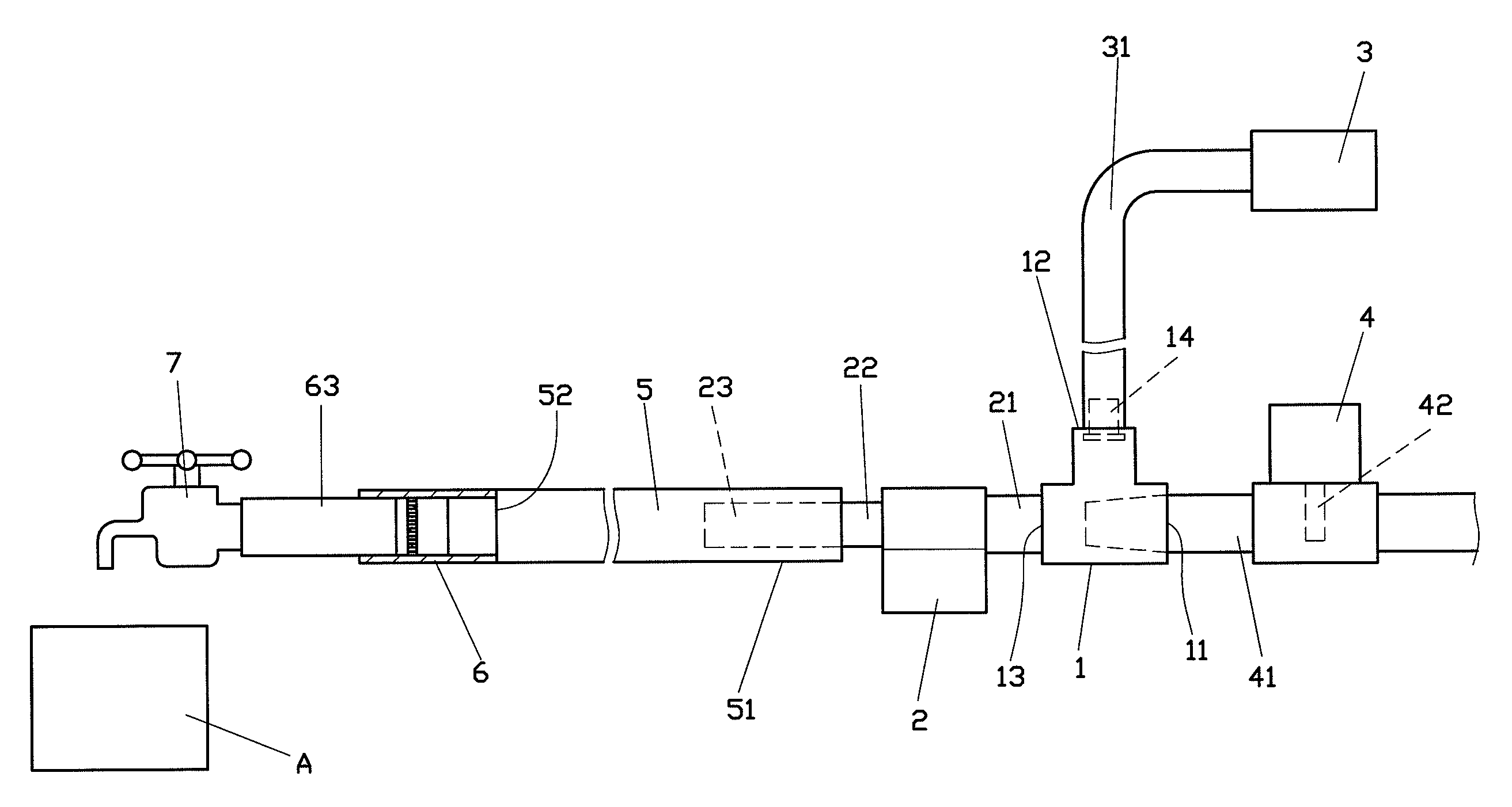
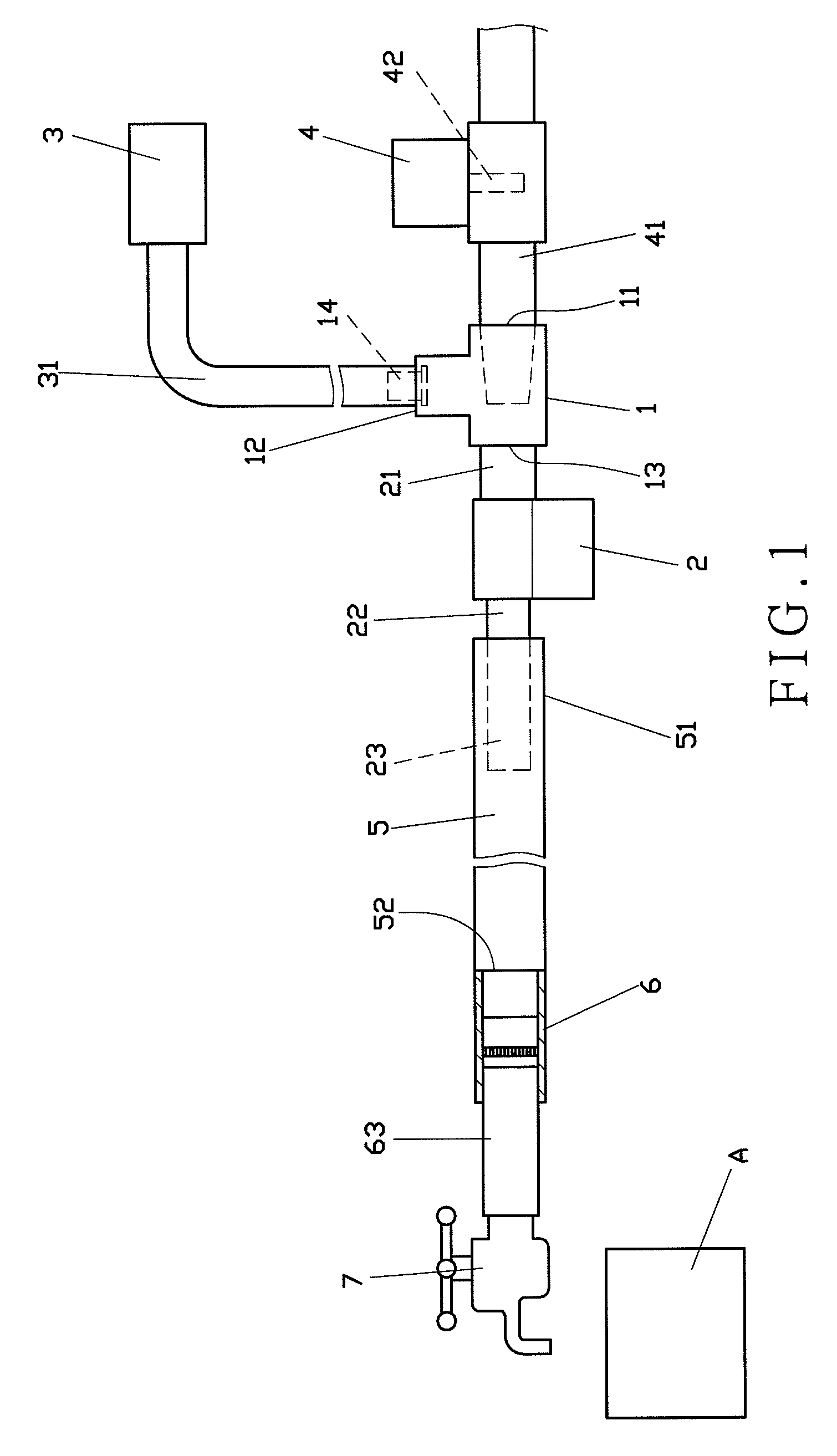
[0026]Referring to FIG. 1, a microbubble water generator in conformity with the present invention includes a gas absorbing device 1, a pressure conveying motor 2, a gas supplier 3, a water switch 4, a booster pipe 5, a pressure release coupling 6, and a water output valve 7.

[0027]The gas absorbing device 1 comprises a liquid entrance 11, a gas entrance 12, and an admixture exit 13 which are communicated with each other. The liquid entrance 11 has an interior opening formed of a gradually narrower contour, so as to speedup the flowing of introduced liquid and thence create a negative pressure. Furthermore, the gas entrance 12 has an anti-reflux valve 14 disposed therein for entrance of gas without counterflow.

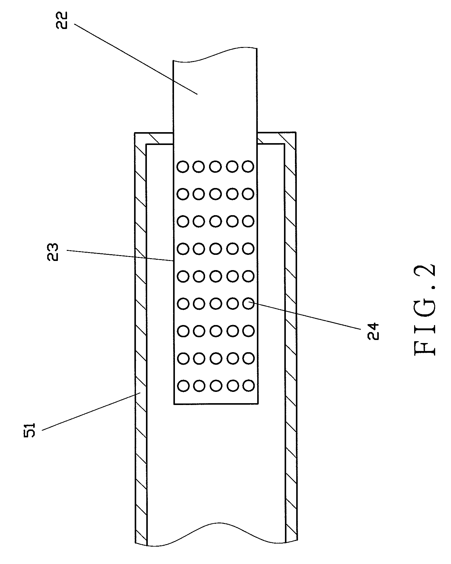
[0028]The pressure conveying motor 2 communicates with the gas absorbing device 1. The pressure conveying motor 2 comprises a first pipe 21 and a second pipe 22. The first pipe 21 is connected with the admixture exit 13 of the gas absorbing device 1. Preferably, a gas diffusing ...


PUM

PropertyMeasurementUnit
pressureaaaaaaaaaa
flow speedaaaaaaaaaa
coloraaaaaaaaaa

Abstract

A microbubble water generator includes a gas absorbing device respectively communicating with a pressure conveying motor, a gas supplier and a water switch. Wherein, the water switch is electrically connected with the pressure conveying motor and the gas supplier, and the pressure conveying motor communicates with a booster pipe. The booster pipe is further connected to a pressure release coupling, and the pressure release coupling thence joints to a water output valve, thereby outputting microbubble water with even and fine properties.

Description

BACKGROUND OF THE INVENTION[0001]1. Field of the Invention[0002]The present invention relates to a microbubble water generator, in particular to one applying a booster pipe to promote an admixture of gas and liquid for giving a rinsing object.[0003]2. Description of the Related Art[0004]A conventional bubble water generator commonly serves to directly introduce gas into water and allows the admixture of gas and water therefrom, which is so called the microbubble water. A typical technique especially includes a motor assembly mounted inside the generator and utilizes the rotation of a motor fan attempting to stir gas into water and so to attain bubble particles smaller than ones created by directly mixing gas and water. Whereas, the problem is that the bubble particles are not in a constant shape, so the typical invention still fails to efficiently diffuse the gas throughout the water in an even and tenuous manner and substantially confines effects on the application to water quality...

Claims


Application Information

Patent Timeline
Patent Type & Authority Patents(United States)
IPC IPC(8): B01F3/04
CPCB01F3/0446B01F5/0415B01F5/043B01F5/0682B01F5/0689B01F23/232B01F25/3121B01F25/31243B01F25/45211B01F25/45
Inventor TSAI, YIH-JIN
Owner TSAI YIH JIN
Why Eureka
Try Eureka