Linear compressor

a linear compressor and compressor technology, applied in the direction of piston pumps, positive displacement liquid engines, pump components, etc., can solve the problems of increased manufacturing costs, complicated and lengthy manufacturing processes, and large mechanical loss of such motion conversion, so as to reduce the number of mainsprings used for linear compressors, reduce the overall cost of part production, and simplify the installation procedure

Active Publication Date: 2012-11-06
LG ELECTRONICS INC
View PDF7 Cites 16 Cited by
  • Summary
  • Abstract
  • Description
  • Claims
  • Application Information

AI Technical Summary

Benefits of technology

[0033]The present invention linear compressor with the configuration described above is characterized in that its linearly-reciprocating movable member is elastically supported on both sides by plural front mainsprings and one single rear mainspring. That is, the number of mainsprings used for the linear compressor has been reduced, thereby contributing to a reduction in an overall cost of part production and to a simplified installation procedure.
[0034]In the linear compressor of the present invention, the linearly reciprocating movable member with separate mass members added thereto is installed at a predetermined distance away from the outer diameter of the mainsprings not to be interfered / overlapped with them. Therefore, although mass members may have been added to the movable member, the mainsprings would not displace from their initial positions. Now that a resonance frequency is easily synchronized with an operating frequency of the linear motor, running conditions of the linear compressor can be managed as efficiently as possible, inconveniences in additional changes / modifications in design for synchronization of the resonance frequency with the operating frequency are reduced, and stroke length of the piston can be increased to enhance the compression efficiency.
[0035]Moreover, the spring guider of the linear compressor has a holder with cavities each of which provides as an escape structure to a fastening bolt, so the rear mainspring can be settled in a stable manner.

Problems solved by technology

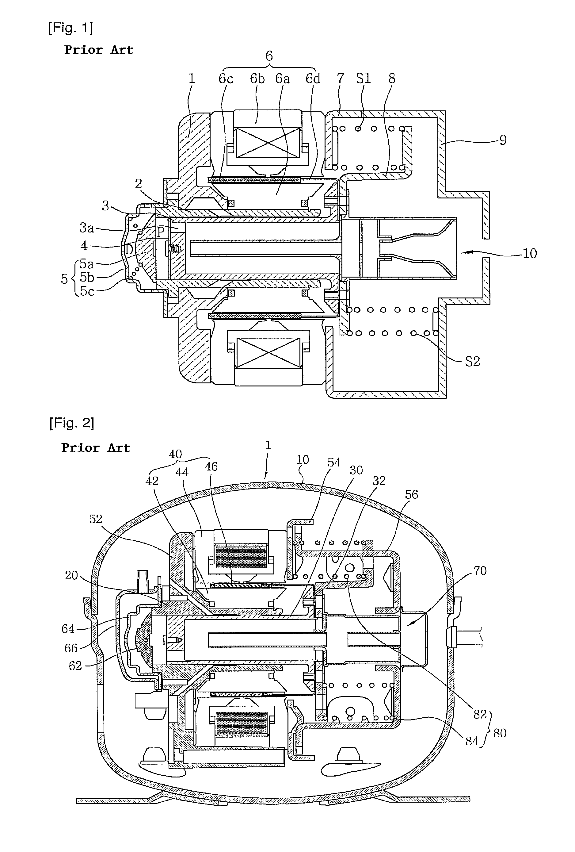
Most reciprocating compressors today has a component like a crankshaft to convert a rotation force of a drive motor into a linear reciprocating drive force for the piston, but a problem arises in a great mechanical loss by such motion conversion.
These pose certain problems such as complicated and lengthy manufacturing process and increased manufacturing costs.
That is, when someone changes a total mass of the movable member trying to synchronize the resonance frequency with the operating frequency, wanted or not, stiffness of the gas spring varies and this in turn makes it hard to synchronize the resonance frequency with the operating frequency.
Therefore, a problem situation is created where it is difficult to manage running conditions of the linear compressor as efficiently as possible, the compression efficiency is degraded, the manufacturing process becomes more complicated as additional changes have to be made in design, and the shorter stroke length of the piston 3 also impairs an overall compression efficiency.
Because of that, an overall manufacturing process gets complicated and lengthy, and manufacturing costs are high.
This actually causes an unnecessary interference or friction of the mainsprings to give rise to problems like noise and damages on the mainsprings.

Method used


Image

  • Linear compressor
  • Linear compressor
  • Linear compressor

Examples


Embodiment Construction

[0054]Hereinafter, preferred embodiments of the present invention will be described in detail with reference to the accompanying drawings.

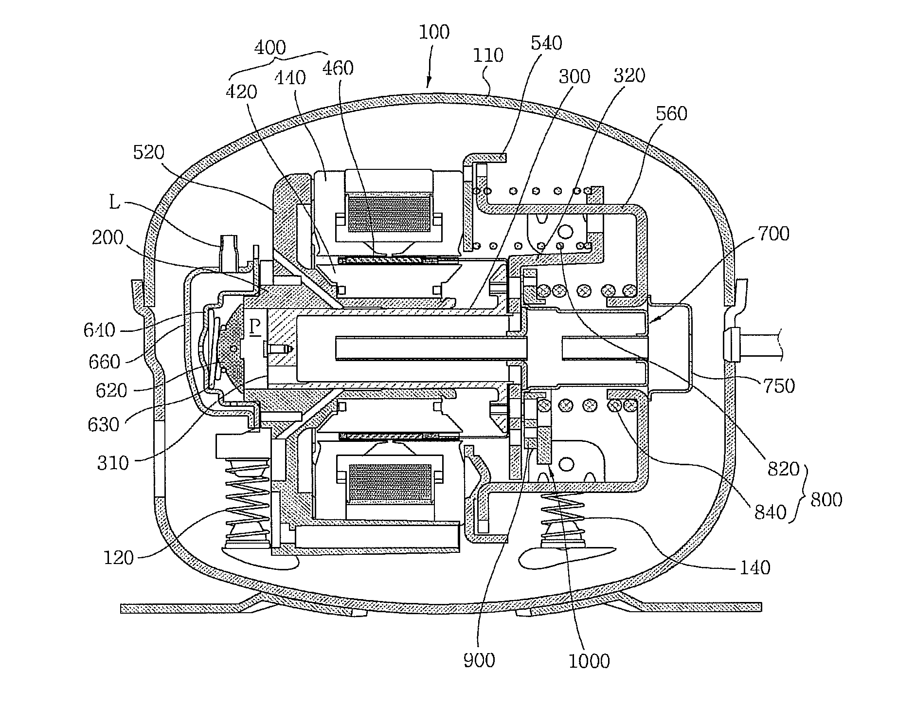
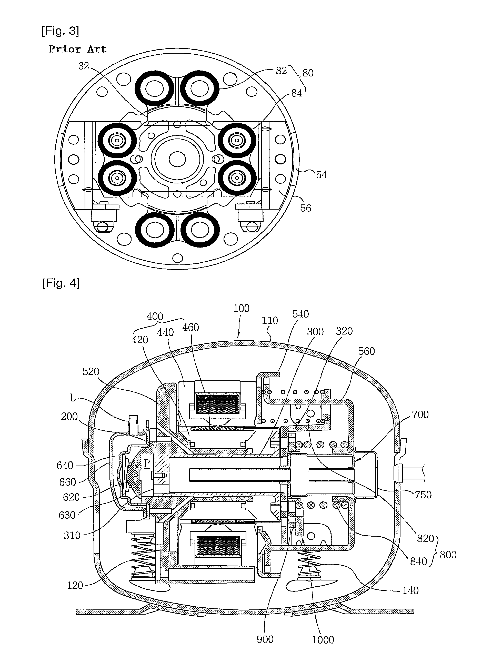
[0055]FIG. 4 illustrates a linear compressor in accordance with one embodiment of the present invention. One embodiment of a linear compressor

[0056]100 in accordance with the present invention includes a cylinder 200, a piston 300, a linear motor 400 provided with an inner stator 420, an outer stator 440, and a permanent magnet 460, and mass members 1000, each being housed in a shell 110 serving as a hermetic casing. When the permanent magnet 460 linearly reciprocates by an interactive electromagnetic force between the inner stator 420 and the outer stator 440, the piston 300 connected to the permanent magnet 460 engagedly moves along the permanent magnet 460, making a linear reciprocating motion.

[0057]The inner stator 420 is affixed to an outer periphery of the cylinder 200, and the outer stator 440 is secured axially by a frame 520 and a motor c...


PUM


Abstract

A linear compressor is provided in which a resonance frequency may be synchronized with an operating frequency. The linear compressor may include a fixed member including a cylinder, a movable member including a piston for compressing refrigerant in the cylinder, a center portion that coincides with the center of the piston, and a support that extends in a radial direction of the piston and linearly reciprocates about the fixed member, a plurality of front mainsprings arranged symmetrically about the center of the piston and each having one end supported on a front side of the support of the supporter and the other end supported on the fixed member, a single rear mainspring having one end supported on a rear side of the supporter and the other end supported on the fixed member, and a plurality of mass members coupled to a rear side of the supporter at a predetermined distance from the outer diameter of the rear mainspring.

Description

TECHNICAL FIELD[0001]The present invention relates in general to a linear compressor, and more particularly, to a linear compressor provided with three mainsprings having a resonance frequency synchronized with an operating frequency, where the resonance frequency can be adjusted without varying initial positions of mainsprings although an additional mass member may be added.[0002]Further, the present invention relates to a linear compressor, which is provided with three mainsprings having a resonance frequency synchronized with an operating frequency of the linear compressor and a rear mainspring installed in a stable manner.BACKGROUND ART[0003]In general, a reciprocating compressor is designed to form a compression space to / from which an operation gas is sucked / discharged between a piston and cylinder, and the piston linearly reciprocates inside the cylinder to compress refrigerants.[0004]Most reciprocating compressors today has a component like a crankshaft to convert a rotation ...

Claims


Application Information

Patent Timeline
Patent Type & Authority Patents(United States)
IPC IPC(8): F04B17/04
CPCF04B39/0088
Inventor KANG, YANG-JUNJEON, YOUNG-HOAN
Owner LG ELECTRONICS INC
Why Eureka
Try Eureka