
Specimen holder having alignment marks

a technology of alignment marks and specimen holders, which is applied in the field of microscopes, can solve the problems of large vacuum volume, difficult to manufacture optical microscopes in vacuum-compatible construction, and especially complex combinatorial microscopes, and achieve the effect of simplifying the automatic finding of this structur

Active Publication Date: 2012-11-06
CARL ZEISS SMT GMBH +1
View PDF9 Cites 5 Cited by
  • Summary
  • Abstract
  • Description
  • Claims
  • Application Information

AI Technical Summary

Benefits of technology

The invention provides a specimen carrier for microscopy that can be used in both optical microscopy and particle beam microscopy. The carrier has at least one alignment mark that is detectable from both sides, making it easier to align the microscope with the object. The carrier has a window that allows for optical microscopy and particle beam microscopy, and the object is held on the carrier and can be fixed in place. The carrier can be calibrated with the position of the microscope, making it easier to examine the object in both microscopy methods. The alignment marks are L-shaped marks that are easily recognized and the mark orientation is clearly identified. The invention provides a more versatile and efficient tool for microscopy examination.

Problems solved by technology

Such combination microscopes are especially complex because the optical microscope must be completely incorporated in the vacuum chamber which is required for the particle beam microscope, and a specimen stage must be provided which moves the specimen between the two microscopes in the vacuum.
The result is a relatively large vacuum volume and, moreover, considerable complexity in the production of the optical microscope which must be manufactured in a vacuum-compatible construction.
A further disadvantage is that an optical imaging with immersion is not possible in the vacuum.
If one forgoes the arrangement of the object in the vacuum in particle beam microscopy, as for example in the combination microscope according to United States patent application publication 2008 / 0030873 A1, the image quality will suffer because the electrons are scattered by a membrane as well as by the air.
First, the transfer is time-consuming and involves the danger of that the specimen will be damaged or destroyed.
Further, the position referencing in both microscopy methods is difficult because the position of a region examined, for example, with optical microscopy must first be re-located for the particle beam microscopy.
Even the use of markers in the object or on the biological specimen does not help here, because the specimen structure generally changes during transfer, for example, resulting from strain.
A time-consuming and tedious relocating of the region previously examined with the other microscopy procedure is thus unavoidable.
Even the finder grids known from transmission electron microscopy, that is round specimen nets whose net grid quadrants are marked, for example, numbered, do not solve this problem, because it is practically impossible to transfer a finder grid between two microscope platforms in the exact orientation.
The position-precise recognition of a particular specimen region on the finder grid with a second microscope platform is thus hardly possible.
In DE 10 2009 020663, the alignment marks are arranged as structures on the non-transparent holder, which fact has the disadvantage that the holder surface must be manufactured with a low surface roughness which makes the surface very scratch-sensitive.
As a result of the scratch sensitivity, the holder may quickly become unusable if the mark gets damaged.
Furthermore, an applied mark is very low-contrast under a stereo microscope, which fact makes the automatic calibration almost impossible.
The risk of soiling is very high with applied marks.
Such fine structures cannot be cleaned in an ultrasonic bath either, which makes it very difficult to automatically calibrate the mark, in particular, in the electron microscope.
All these problems in connection with applied marks make the re-use of the holder almost impossible in different microscopy methods and specimens.
A further disadvantage is that when the alignment marks are arranged on the non-transparent holder as structures, the position of the mark can only be seen from one side of the holder.

Method used


Image

  • Specimen holder having alignment marks
  • Specimen holder having alignment marks
  • Specimen holder having alignment marks

Examples


Embodiment Construction

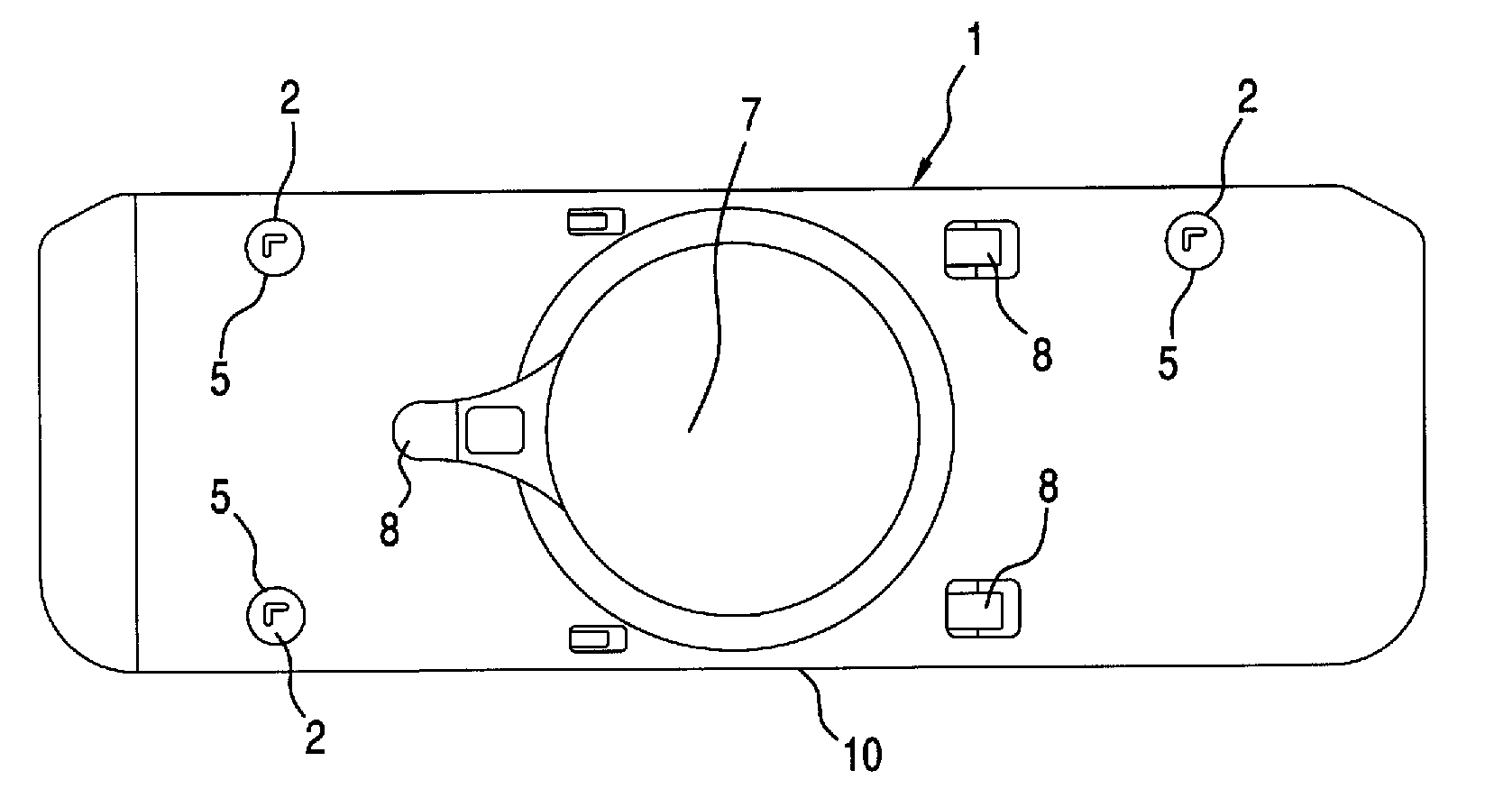
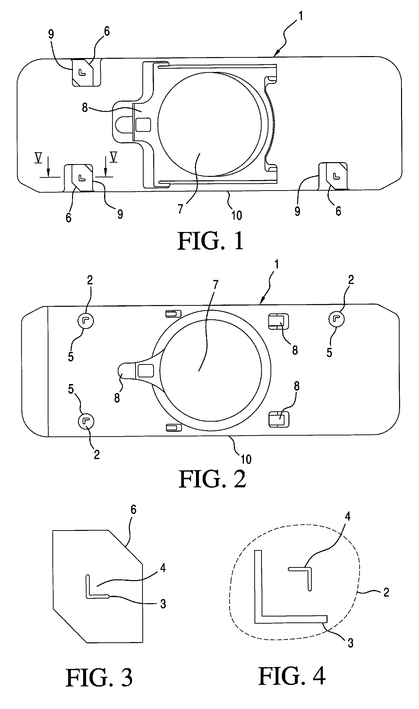
[0028]FIG. 1 shows the top of a specimen carrier 1 by means of which an object, for example, a biological specimen, can be examined with a combination of light microscopy and electron beam microscopy. The specimen carrier 1 is configured as a metallic holder 10 which has the outer dimensions of a standard glass object carrier. It is, for example, 75.5 mm long and 25.5 mm wide. Such dimensions allow an especially simple use of the specimen carrier 1 in a conventional light microscope. Where applicable, other dimensions for the specimen carrier 1 are of course also possible and advantageous, depending on the application.

[0029]The specimen carrier 1 has a window 7 configured as a complete aperture through the plate-shaped specimen carrier 1 in a central region in which typically a glass object carrier would be used. A typical cover glass which is fixed over the window 7 with a spring 8 is used as the object carrier element.

[0030]The specimen carrier 1 further has three equivalent reces...


PUM


Abstract

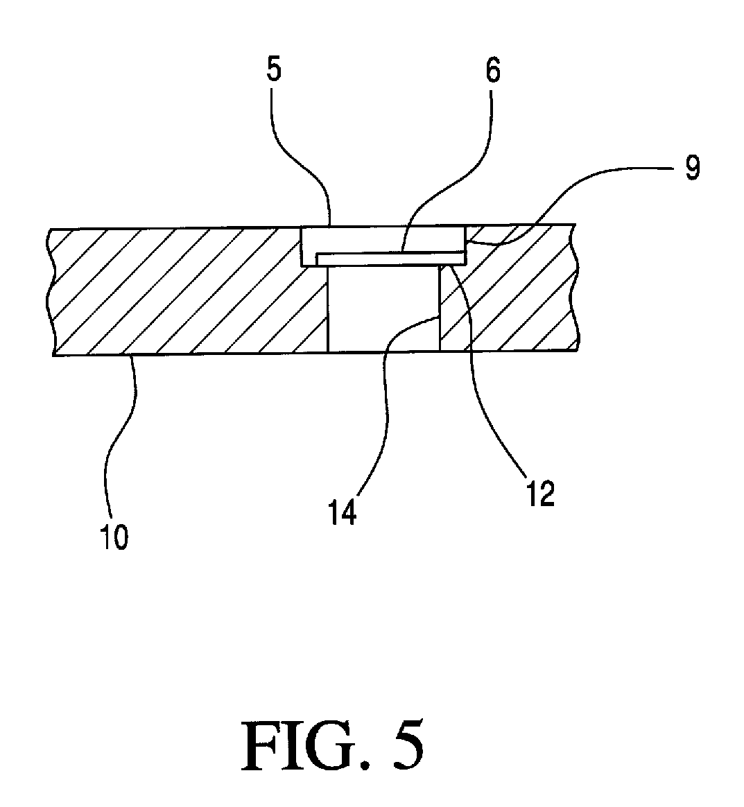
For the microscopy of an object or a specimen with a combination of optical microscopy and particle beam microscopy, an electrically conducting specimen carrier (1) is used which is configured for use in a particle beam microscope as well as in an optical microscope and has at least one alignment mark (2). The alignment mark is configured as a pass-through structure and is detectable from the top and from the bottom of the specimen carrier.

Description

CROSS REFERENCE TO RELATED APPLICATION[0001]This application claims priority of German patent application no. 10 2010 052 674.6, filed Nov. 24, 2010, the entire content of which is incorporated herein by reference.FIELD OF THE INVENTION[0002]The invention relates to the microscopy of an object with a combination of optical microscopy and particle beam microscopy.BACKGROUND OF THE INVENTION[0003]An examination with optical microscopy, for example, with light microscopy as well as with particle beam microscopy, for example, with electron microscopy, is often desirable, in particular for biological or material-science specimens. In the state of the art, complex microscopes which can carry out both types of microscopy methods are used. Such a microscope is known, for example, from EP 0849765 A2 or the U.S. Pat. No. 6,683,316 B2. Such combination microscopes are especially complex because the optical microscope must be completely incorporated in the vacuum chamber which is required for t...

Claims


Application Information

Patent Timeline
Patent Type & Authority Patents(United States)
IPC IPC(8): G02B21/34H01J37/26H01J37/20
CPCG02B21/34
Inventor HEISE, HEINONOLTE, ANDREASTHOMAS, CHRISTIANEDELMANN, MARTINWOLF, UWEKOHLHAAS, ULRICHLYSENKOV, DMITRY
Owner CARL ZEISS SMT GMBH
Learn More